Turbine disk tenon and groove drilling device and turbine disk tenon and groove drilling method

A technology for drilling devices and turbine discs, which is applied in the direction of drilling/drilling equipment, turbines, and drilling molds for workpieces, etc., which can solve the problem of high surface symmetry and cannot guarantee the technology of mortise and groove bottom holes to be processed Requirements and other issues to achieve high-precision positioning and eliminate positioning errors

Active Publication Date: 2019-05-14
CHINA HANGFA GUIZHOU LIYANG AVIATION POWER CO LTD
View PDF9 Cites 0 Cited by
  • Summary
  • Abstract
  • Description
  • Claims
  • Application Information

AI Technical Summary

Problems solved by technology

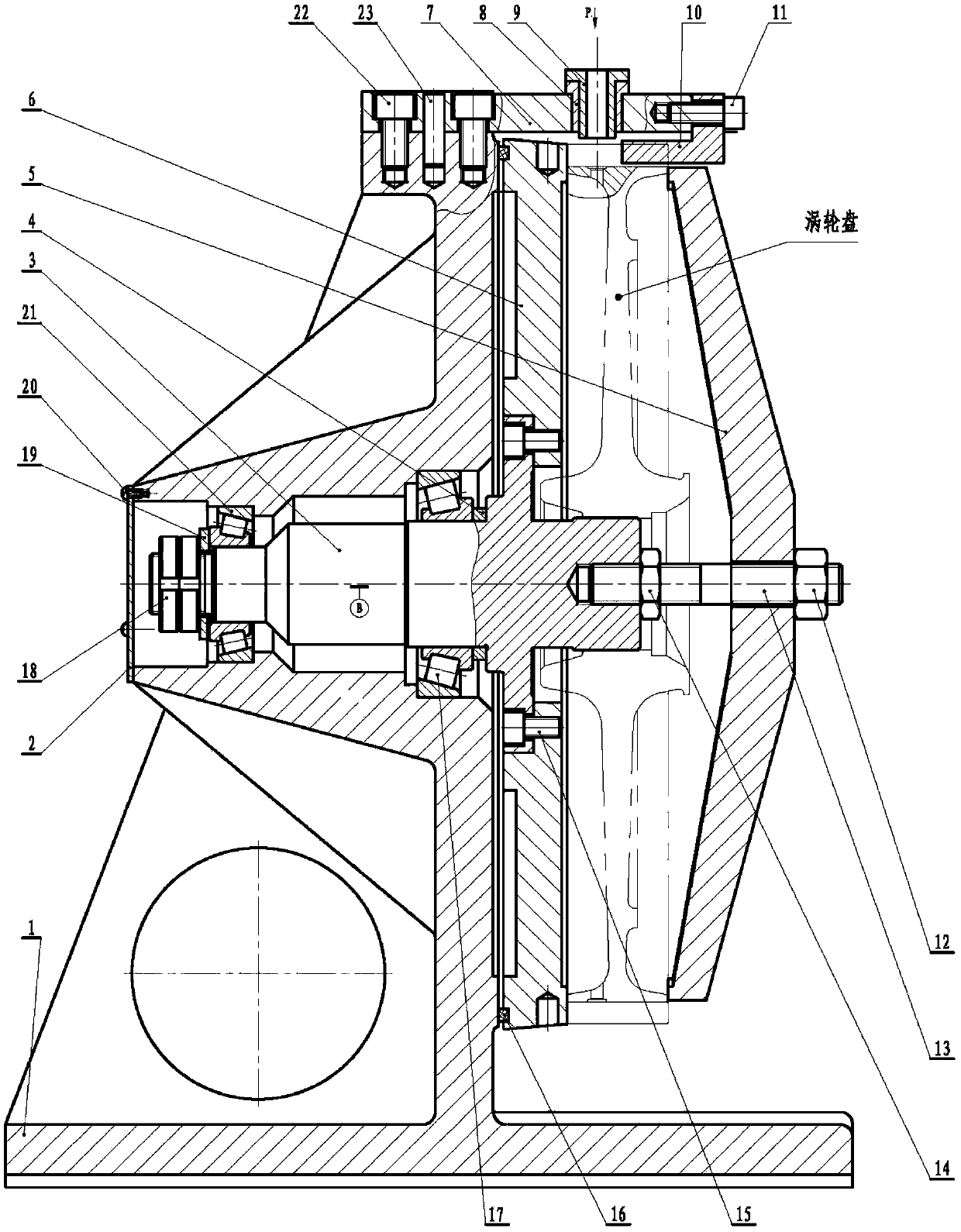
However, in the drilling process of the bottom of the tenon and groove of a new type of aero-engine turbine disk, there is a positioning error between the tenon and groove positioning block 10 in the existing device and the tenon and groove of the turbine disk. There is also an error between the guiding mechanism composed of sleeve 8 and drill sleeve 9, resulting in the accumulation of systematic errors. However, the symmetry of the tenon and groove center plane of a new type of aero-engine tenon and groove bottom hole is relatively high, and the system error of the existing device After accumulating, the technical requirement of higher symmetry of the processed tenon-groove bottom hole to the tenon-groove center plane cannot be guaranteed

Method used


Image

  • Turbine disk tenon and groove drilling device and turbine disk tenon and groove drilling method
  • Turbine disk tenon and groove drilling device and turbine disk tenon and groove drilling method
  • Turbine disk tenon and groove drilling device and turbine disk tenon and groove drilling method

Examples


Embodiment Construction

[0031] Attached below Figure 4 ~ Figure 12 The present invention is described in further detail to the specific embodiment of the present invention:

[0032] A turbine disk tongue and groove drilling device, base 1, cover plate 2, mandrel 3, adjustment pad 4, pressure plate 5, disk 6 for supporting the turbine disk, drilling template 7, bushing 8, drill sleeve 9, First nut 12, stud 13, second nut 14, first screw 15, sealing ring 16 for sealing between disc 6 and base 1, first bearing 17, third nut 18, washer 19, second Screw 20, second bearing 21, third screw 22, cylindrical pin 23, locking nut 24, tightening nut 25. Screw in tightening nut 25, locking nut 24 on bushing 8; Drill bushing 9 inserts in the bottom hole 7b of drilling template 7 from below drill template 7, also can directly put into directly from the straight groove 7a of drill template 7; After the groove 8b of the bushing 8 corresponds to the platform 9b of the drill bushing 9, insert the bushing 8 between th...


PUM


Abstract

The invention discloses a drilling device and a turbine disk mortise drilling method. The drilling device comprises a drill jig plate (7), a bushing (8) and a drill sleeve (9). The bushing (8) is arranged in a bottom hole (7b) of the drill jig plate (7), the drill sleeve (9) is arranged in the bushing (8), and the bushing (8) is connected with a tightening nut (25) and a locking nut (24) through ascrew thread (8a) sequentially through bottom to top. In use, the tightening nut (25) is tightened, the drill sleeve (9) is lifted up through the bushing (8), a mortise positioning face (9a) of the drill sleeve (9) is attached to a mortise to eliminate a mortise positioning clearance, and the locking nut (24) is tightened. The drilling device has the advantages that turbine disk mortise positioning errors are fewer and it can be guaranteed that a bottom hole of a machined mortise is highly symmetric to a mortise center face.

Description

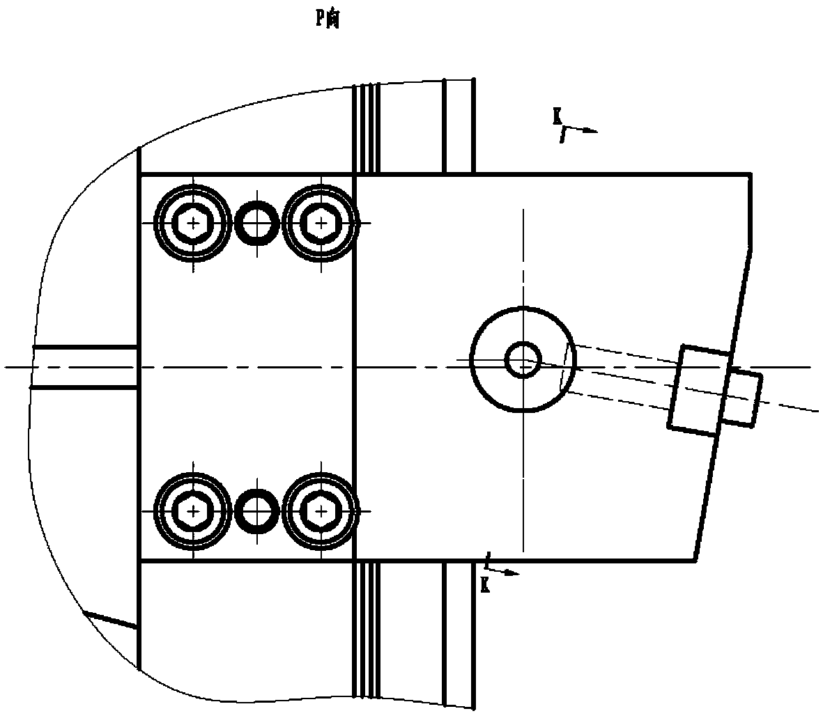
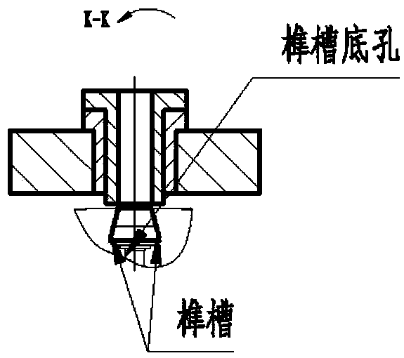
technical field [0001] The invention belongs to the technical field of aero-engine manufacturing, and in particular relates to a device for drilling the bottom of a tenon-groove of an aero-engine turbine disk and a method for drilling a turbine disk tenon-groove. Background technique [0002] In the drilling process of the tenon and groove bottom of the aero-engine turbine disk, the existing tenon and groove bottom hole drilling device is mainly the indexing type of the tenon and groove positioning block, and its structural principle is shown in Figure 1 ~ Figure 3 , it mainly consists of base 1, cover plate 2, mandrel 3, adjusting pad 4, pressure plate 5, disc 6, drill template 7, bushing 8, drill sleeve 9, tongue and groove positioning block 10, screw 11, first nut 12. Stud 13, second nut 14, first screw 15, sealing ring 16, first bearing 17, third nut 18, washer 19, second screw 20, second bearing 21, third screw 22 and cylindrical pin 23 compositions. Its working princ...

Claims


Application Information

Patent Timeline
Patent Type & Authority Patents(China)
IPC IPC(8): B23B47/28B23B49/02B23B35/00
CPCB23B35/00B23B47/28B23B49/02B23B2215/76B23B2247/12
Inventor 王庆齐刘再贵
Owner CHINA HANGFA GUIZHOU LIYANG AVIATION POWER CO LTD
Why Eureka
Try Eureka