Power generation system of wheel potential energy

A power generation system and wheel technology, applied in the direction of electromechanical devices, electrical components, electric components, etc., can solve the problems of destroying the original structure, difficulty in implementation, large volume of shaft end stators and stator clutches, etc., and achieve fuel saving, manufacturing and installation. Easy, huge social economic and environmental benefits

Inactive Publication Date: 2011-01-26
陈冠卿
View PDF4 Cites 0 Cited by
  • Summary
  • Abstract
  • Description
  • Claims
  • Application Information

AI Technical Summary

Problems solved by technology

The main disadvantage of this invention application is that the shaft end stator and the stator clutch are relatively large in size, which greatly affects and destroys the original structure of the relevant parts on the vehicle, so it is difficult to implement on vehicles such as cars.

Method used


Image

  • Power generation system of wheel potential energy
  • Power generation system of wheel potential energy
  • Power generation system of wheel potential energy

Examples


Embodiment Construction

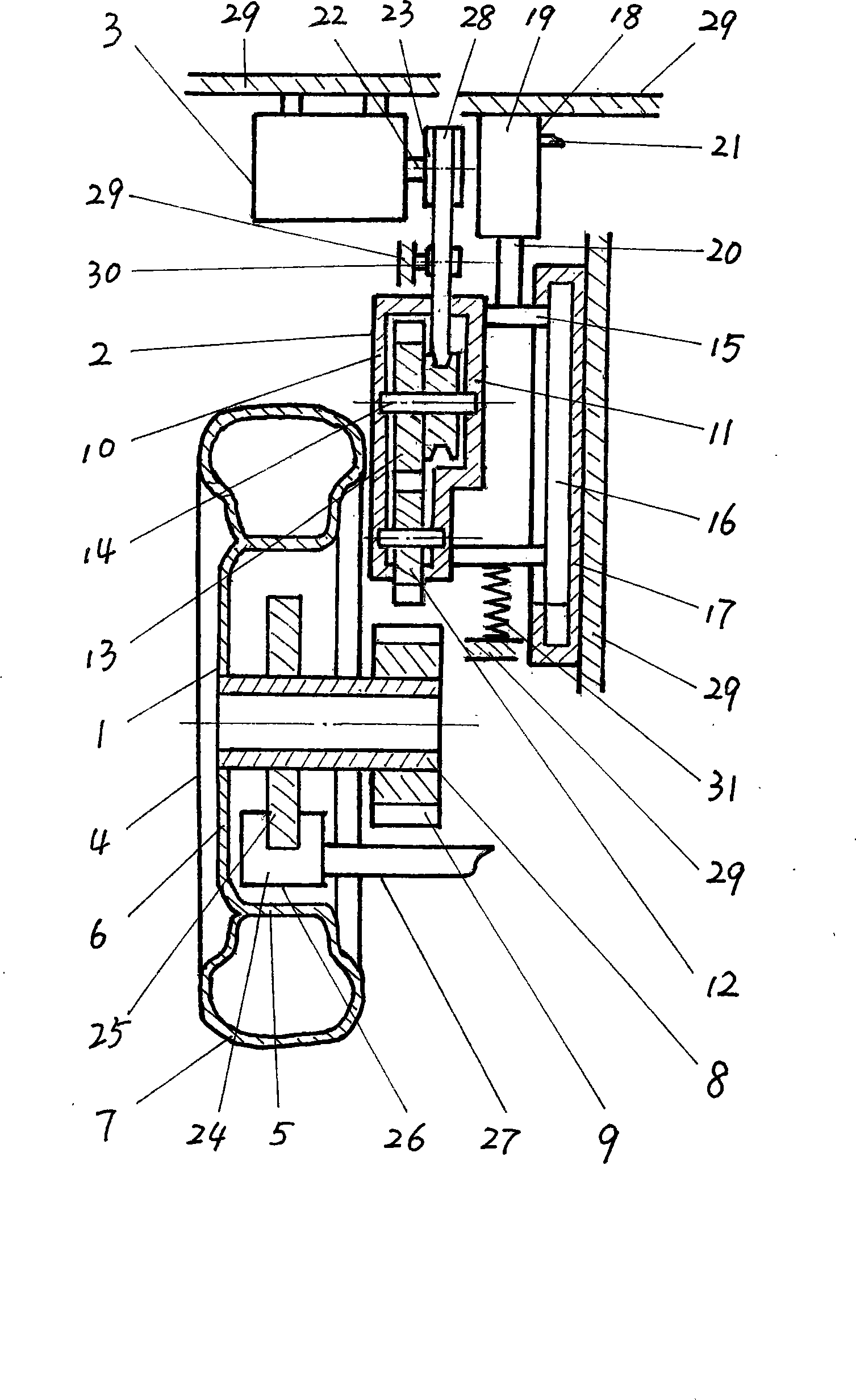
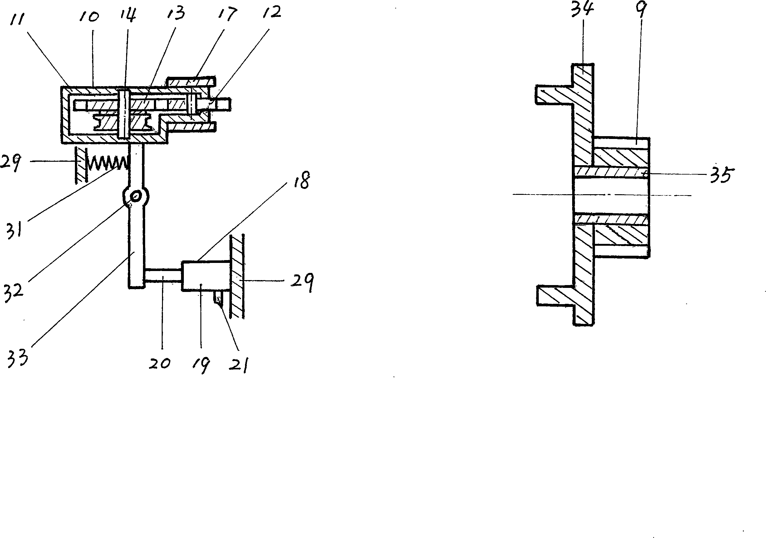
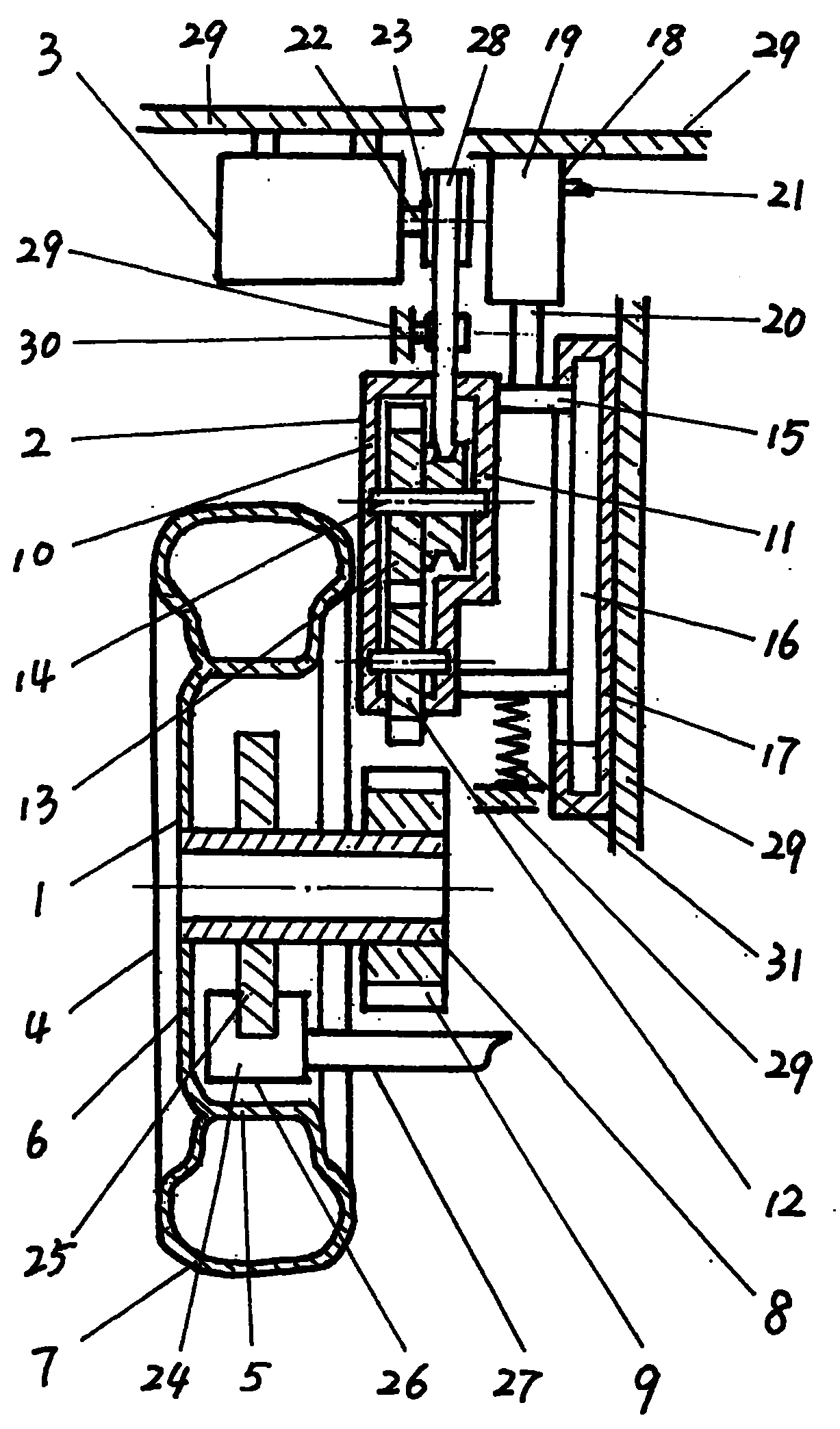
[0015] In Fig. 1, 1 is a wheel potential energy collection device, 2 is a potential energy transmission clutch device, and 3 is a generator. The wheel potential energy collection device 1 is composed of a wheel 4 , a mining wheel 9 and a disc brake 24 . The wheel 4 is composed of a rim 5 , spokes 6 , tires 7 and a hub 8 . On the wheel hub 8, the mining wheel 9 is installed. The disc brake 24 is composed of a disc 25 , a caliper 26 and a caliper arm 27 . Brake caliper 26 is installed on one end of brake caliper arm 27, and the other end is installed on the vehicle frame chassis or on the axle. The driving wheel 9 is a gear, and if necessary, it can also be installed on the rim 5 of the wheel 4, the spoke 6, the brake disc 25 or on the brake drum. The potential energy transmission clutch device 2 is made up of a transmission wheel frame 10 , a slide groove 17 and a clutch 18 . The drive wheel frame 10 is composed of a drive wheel housing 11, a drive wheel 12, a drive main wh...


PUM


Abstract

The invention discloses a generation system of wheel potential energy which can be used in automobiles, electric vehicles, tractors, trains and some wheel-type military vehicles, belonging to a field of a generation device for vehicles. The invention essentially comprises a collecting device of wheel potential energy, a transmission disconnecting device of potential energy and a generator. The collecting device of wheel potential energy consists of a plurality of wheels, a brake and a collecting motor wheel; the collecting motor wheel is arranged on a wheel hub; the transmission disconnectingdevice of potential energy and the generator are equipped at a proper position on a frame chassis of an automobiles or a train corresponding to the collecting motor wheel of the collecting device of wheel potential energy. The transmission disconnecting device of potential energy comprises a driving wheel frame, a clutch and a sliding groove; under the effect of a control system for the entire vehicle, a driving wheel of the transmission disconnecting device of potential energy and the collecting motor wheel of the collecting device of wheel potential energy can be combined or separated. Whenthe vehicle is on a downhill road, in high-speed driving and in need of deceleration and braking, the collecting motor wheel and the driving wheel can be combined through the control system on the vehicle; since the rotation of wheels can drive the collecting motor wheel to rotate synchronously and cause the driving wheel, a driving main wheel and a generator wheel to rotate together, the generator can work to generate electricity which supplies the vehicle and drives the vehicle as required. The invention is ingenious in structure and convenient in implementation; the invention also developsa new method for applying potential energy, which can save energy, reduce emission, and generate good social and economical benefits of environmental protection.

Description

Technical field [0001] The invention relates to a wheel potential energy generation system that can be applied to various vehicles such as automobiles, trains, electric vehicles, tractors and wheeled military vehicles, and belongs to the field of vehicle power generation equipment. Background technique [0002] In nature, potential energy is ubiquitous. Most of the land on Earth is covered by mountains and hills. Our country is also a country with many mountains and hills. There are mountains and hills, which will inevitably cause the ups and downs of the road. In cities, most of the roads have ups and downs, and the viaducts in some cities also artificially produce the ups and downs of the roads. When the vehicle is running on a road with ups and downs, due to the mass, speed, friction between the wheels and the ground and the gravitational force of the earth, the vehicle will generate a very strong automatic downward driving force when it goes downhill. Dive force is p...

Claims


Application Information

Patent Timeline
Patent Type & Authority Patents(China)
IPC IPC(8): B60K25/08H02K7/18
Inventor 陈冠卿郑同社陈洪涛陈洪波
Owner 陈冠卿
Why Eureka
Try Eureka