Conveying system

A technology for handling systems and power cords, applied in the field of handling systems, which can solve the problems of inconvenient replacement or maintenance of collector rails, generation of dust, wear of components, etc., and achieve the effects of good dust removal, cleanliness maintenance, and simplified components

Inactive Publication Date: 2008-07-16
AU OPTRONICS CORP
View PDF0 Cites 4 Cited by
  • Summary
  • Abstract
  • Description
  • Claims
  • Application Information

AI Technical Summary

Problems solved by technology

Although, the handling system 200 does not have the problems of component wear and dust generation due to contact and friction between the power cord 150 and the linear slider 140, or between the power cord 150 and the auxiliary wheel stand 130
However, the long-term contact between the collector rail 160 and the crane 120 will also produce wear and dust
In addition, it is also quite inconvenient when replacing or maintaining the collector rail 160

Method used


Image

  • Conveying system
  • Conveying system
  • Conveying system

Examples


Embodiment Construction

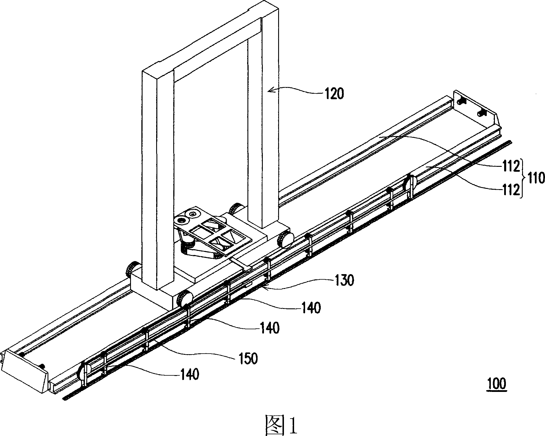
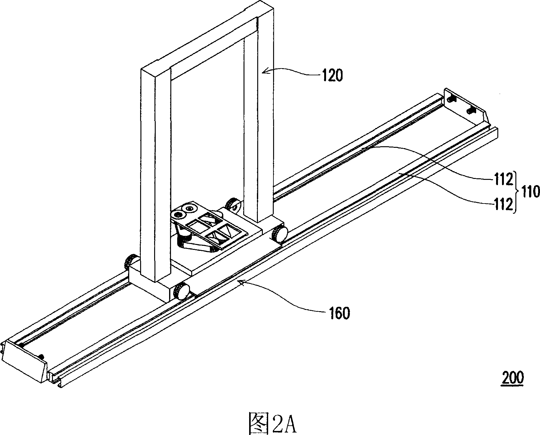
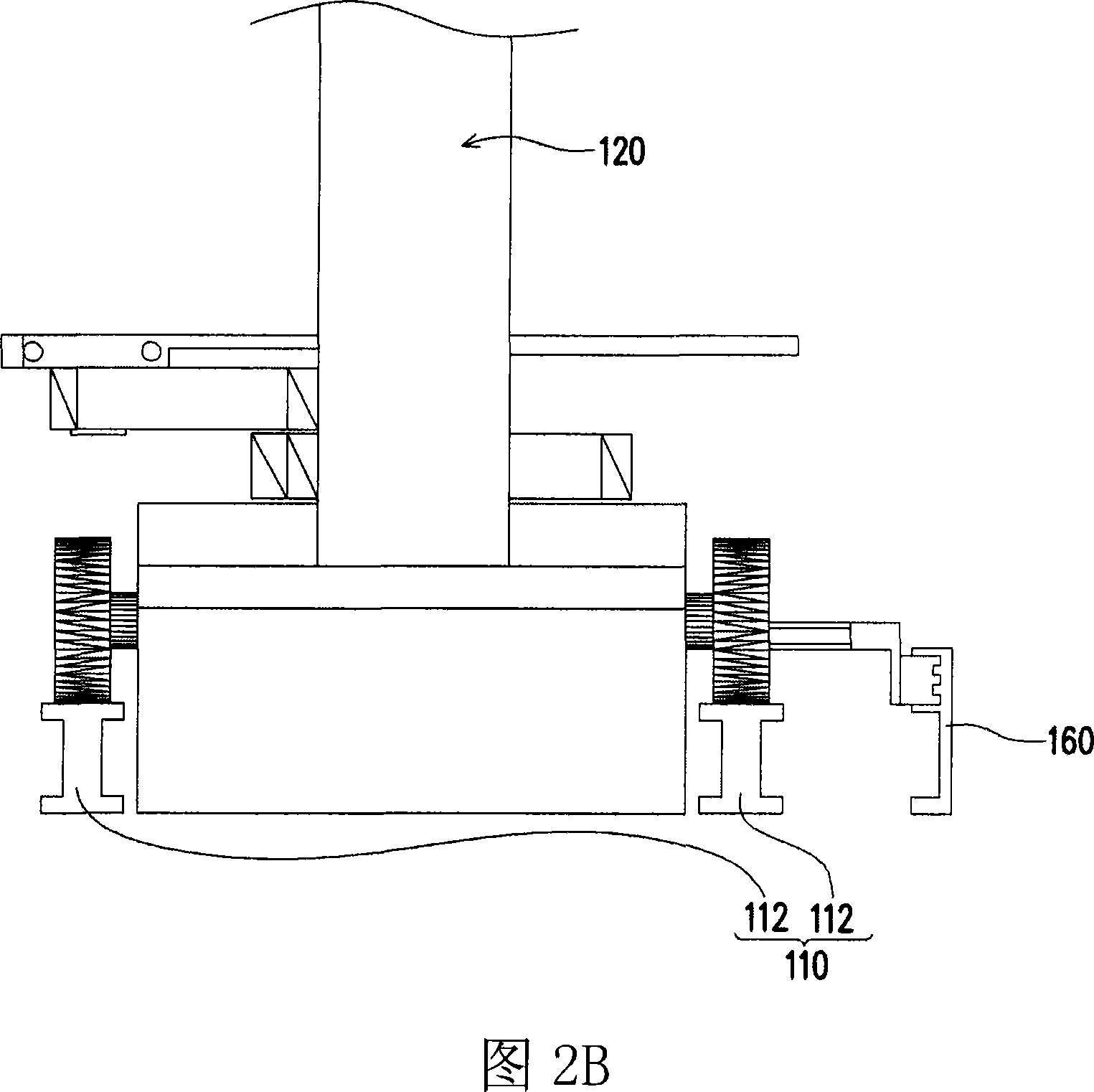
[0033] FIG. 3A is a schematic diagram of a transport system of the present invention, and FIG. 3B and FIG. 3C are partial schematic diagrams of FIG. 3A . Please refer to FIG. 3A , FIG. 3B and FIG. 3C at the same time. The transportation system 300 includes a base 310 , a crane 320 , a power cord receiving device 330 and a power cord 340 . The base 310 has a track 312 . The crane 320 is located on the base 310 and travels along the track 312 . The power cord storage device 330 is disposed at one end of the track 312 , and the power cord 340 is stored in the power cord storage device 330 . In addition, the power line 340 is electrically connected to the crane 320 to supply power to the crane 320 .

[0034] When the power cord 320 provides power to the crane 320 to move the crane 320, since the power cord 340 needs to be electrically connected to the crane 320 to supply power, the power cord 340 needs to cooperate with the crane 320 to move, so as to avoid the power cord 340 br...


PUM


Abstract

The invention discloses a transporting system, which comprises a base, a crane, a withdrawing device of power leads, and power leads. The base has a track. The crane is arranged on the base and travels along the track. The withdrawing device of power leads is arranged on an end of the track. The power leads are withdrawn inside the withdrawing device of power leads, and the power leads are electrically connected with the crane to provide electricity for the crane. By adopting the transporting system of the invention, the dust generating amount during the operation of the transporting system of the invention can be effectively reduced, and a good dust removal method can be provided to effectively keep the cleanness inside the transporting system. In addition, as the components of the transporting system of the invention are simplified, easy and fast assembly and disassembly can be realized and the manufacturing cost of the entire system is reduced.

Description

technical field [0001] The invention relates to a transport system, and in particular to a transport system with low cost, easy installation and suitable for use in a dust-free environment. Background technique [0002] Fig. 1 is a three-dimensional schematic diagram of a conveying system in the prior art. Please refer to FIG. 1 , the transport system 100 includes a base 110 , a crane 120 , a set of auxiliary wheel stands 130 , a plurality of linear slides 140 and a power cord 150 . The base 110 has a track 112 . The crane 120 is located on the base 110 and travels along the track 112 . The linear slider 140 is disposed on the auxiliary wheel stand 130 , and the power cord 150 is disposed on the linear slider 140 and the auxiliary wheel stand 130 . In addition, the power line 150 is connected to the crane 120 to provide power to the crane 120 so that the crane 120 can move on the track 112 . [0003] In detail, when the power cord 150 provides power to the crane 120 to m...

Claims


Application Information

Patent Timeline
Patent Type & Authority Applications(China)
IPC IPC(8): B66C17/06B66C19/02
Inventor 谢承勋李宗和
Owner AU OPTRONICS CORP
Why Eureka
Try Eureka