
Nano material drawing device in scanning electron microscope driven by piezoelectric ceramic piece

A piezoelectric ceramic sheet and scanning electron microscope technology, which is applied in analysis materials, measuring devices, scanning probe technology, etc., can solve problems such as being unfavorable for method popularization, unable to observe changes in microstructure, etc., and achieve reliable performance, low cost, Wide range of effects

Inactive Publication Date: 2008-07-16
BEIJING UNIV OF TECH
View PDF0 Cites 5 Cited by
  • Summary
  • Abstract
  • Description
  • Claims
  • Application Information

AI Technical Summary

Problems solved by technology

This method puts a complex structure into the sample chamber of the transmission electron microscope, which limits the large-angle tilt of the sample stem, and cannot observe changes in the atomic-scale microstructure of the sample that needs to be observed under the positive band axis, which is not conducive to the development of the method. to promote

Method used


Image

  • Nano material drawing device in scanning electron microscope driven by piezoelectric ceramic piece
  • Nano material drawing device in scanning electron microscope driven by piezoelectric ceramic piece

Examples


Embodiment Construction

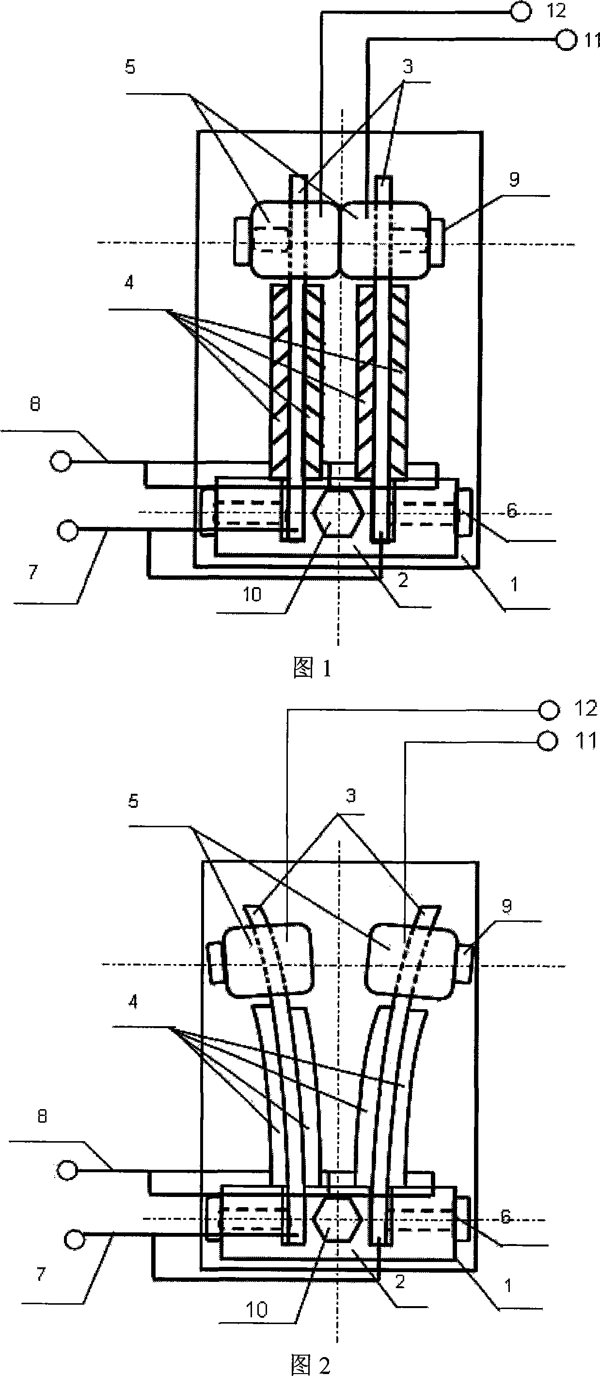
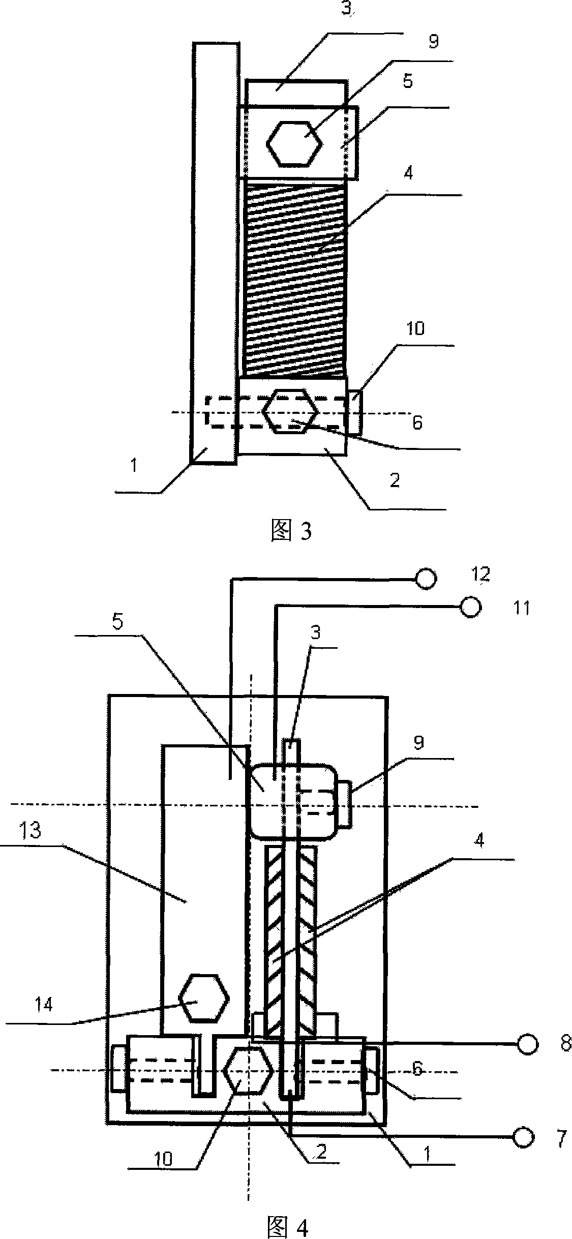
[0022] The nanomaterial stretching device in the scanning electron microscope driven by the piezoelectric ceramic sheet of the present invention includes a base 1 and an insulating support seat 2 with two grooves fixed on the base 1 with screws III10, and two grooves on the insulating support seat 2. One end of the two metal sheets 3 are respectively fixed with screws I6 in each groove, and two piezoelectric ceramic sheets 4 are respectively pasted on both sides of the metal sheets 3, and at the same time, the two sample stages 5 are respectively fixed with screws II9 at the other end of each metal sheet 3. Fixed on each piece of metal sheet 3, connect the negative electrode of the external power supply and the positive electrode of the external power supply through the electrode lead I7, the electrode lead I7 is respectively connected to two metal sheets 3, and the electrode lead II8 is respectively connected to 4 piezoelectric ceramic sheets 4; Adjust the two sample stages 5 ...


PUM


Abstract

A nanometer material stretching device in a scanning electron microscope driven by a piezoceramics plate belongs to the testing field of nanometer material original position. The invention includes a base (1) and an insulating supporting seat (2) with two grooves. The two grooves are respectively fixed at one end of the two metal slices (3). The two sides of the metal slices are respectively stuck with two piezoceramics plates(4) and simultaneously the other end of each metal slice is respectively fixed with two sample platforms(5) and connected with a power cathode through an electrode leader I (7) and connected with an anode through an electrode leader II (8); the electrode leader I (7) is respectively connected with the two metal slices (3); the electrode leader II (8) is respectively connected with four piezoceramics plates(4); the two sample platforms are in a same horizontal plane and the narrow gap between the platforms is between 2 to 50 Mu m. The invention has low cost and is simple and convenient to operate, can measure the charge transport characteristic during the stress straining process of the nanometer material, and provide reliable data for the nanometer material in the fields like a micro-electromechanical system.

Description

technical field [0001] The invention relates to a device for in-situ stretching of nanomaterials in a scanning electron microscope (hereinafter referred to as scanning electron microscope) driven by a piezoelectric ceramic sheet. Electron microscopy can observe the structural changes of nanomaterials during tensile deformation in real time, revealing the deformation mechanism and brittle-ductile transition mechanism of nanomaterials under tensile load. At the same time, an electrode can be added on it to measure the change of the conductance property of the nanomaterial during the deformation process, which belongs to the field of in-situ testing of the mechanical / electrical properties of the nanomaterial. Background technique [0002] One-dimensional nanomaterials (including: nanowires, nanotubes, nanobelts, nanorods, etc.) The incomparable mechanical properties of bulk materials, for example, the superplasticity of a nanomaterial under stress, and the fracture mechanism o...

Claims


Application Information

Patent Timeline
IPC IPC(8): G01N3/00G01N13/10H01J37/26G01Q60/10
Inventor 韩晓东岳永海郑坤张跃飞张泽
Owner BEIJING UNIV OF TECH
Learn More