Slide fastener with automatic stop device

An automatic stop device and zipper puller technology, applied in the field of zipper pullers, can solve problems such as difficult and cheap production, and achieve the effects of simplifying assembly operations, high-speed assembly, and reducing the number of parts

Active Publication Date: 2008-07-23
YKK CORP
View PDF1 Cites 12 Cited by
  • Summary
  • Abstract
  • Description
  • Claims
  • Application Information

AI Technical Summary

Problems solved by technology

Therefore, it is difficult to produce zipper pullers for zippers with automatic stop devices cheaply and at high speed to provide

Method used


Image

  • Slide fastener with automatic stop device
  • Slide fastener with automatic stop device
  • Slide fastener with automatic stop device

Examples


Embodiment 1

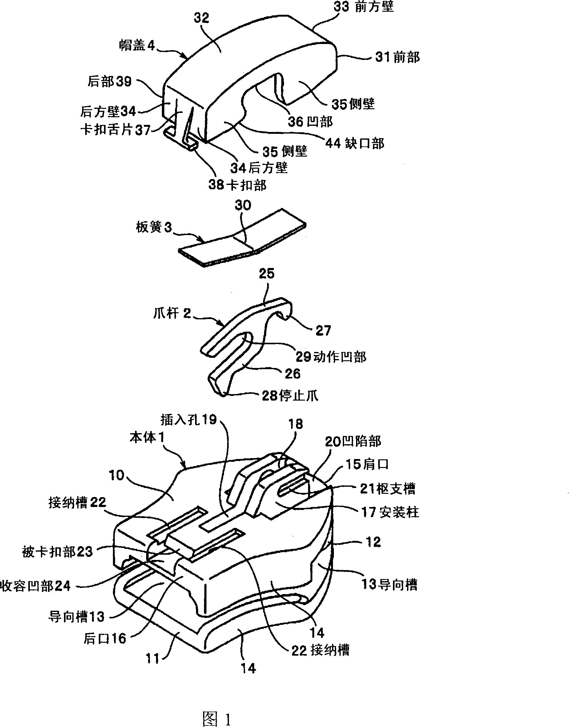
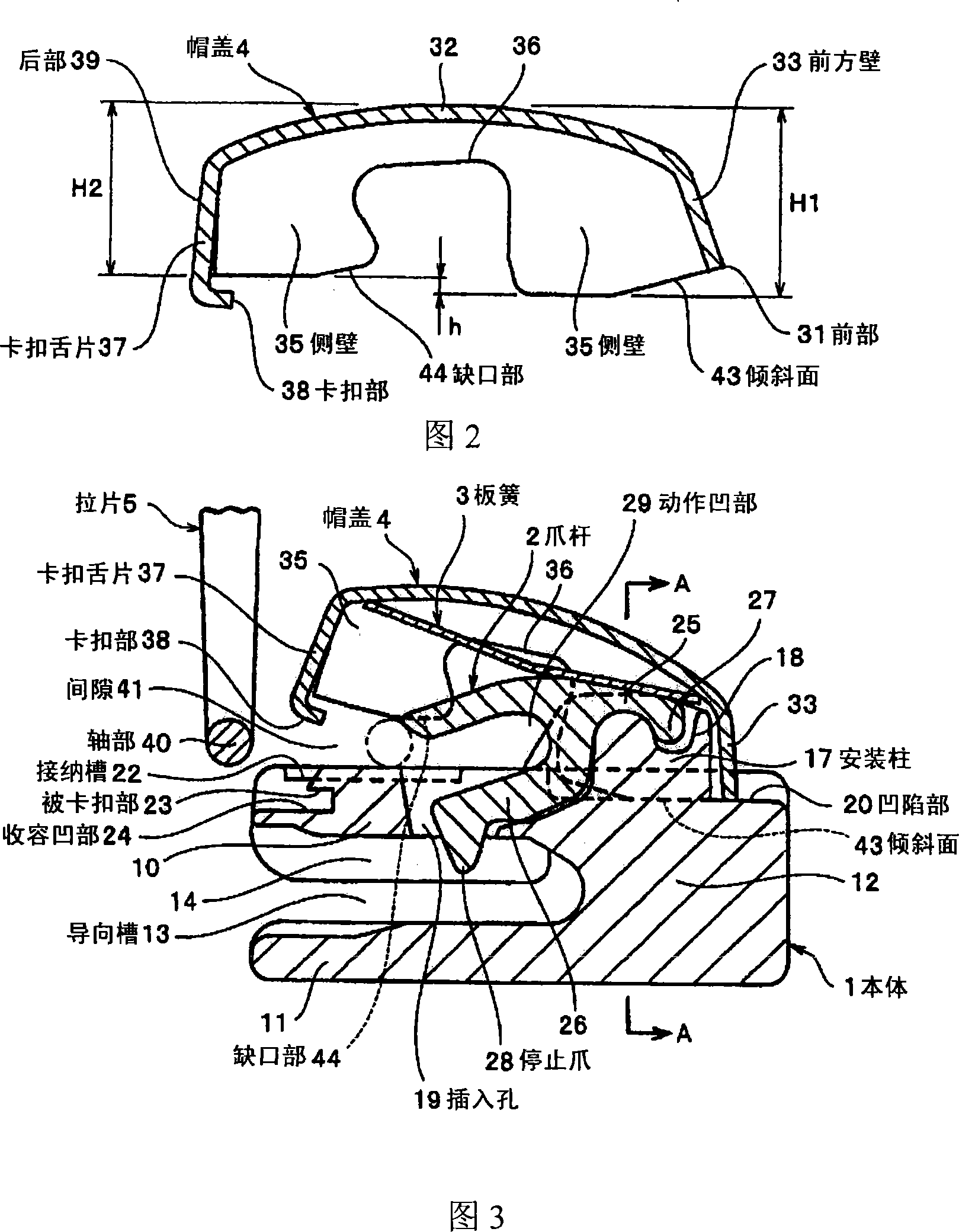
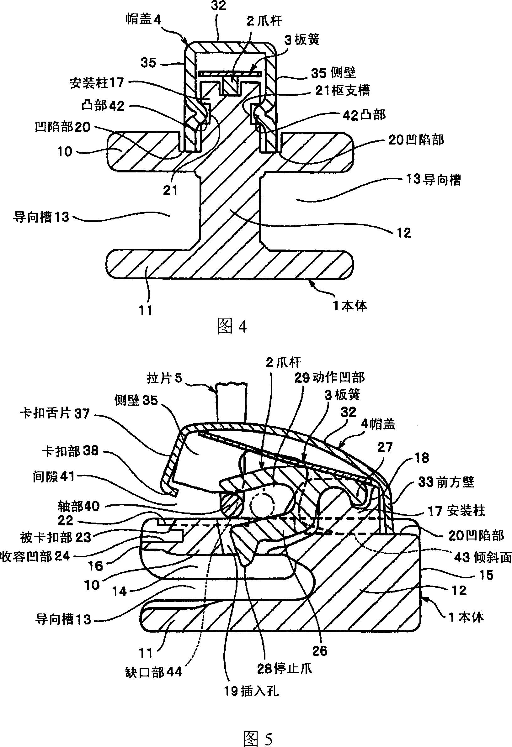
[0044] As mentioned above, the slide fastener puller for a slide fastener with an automatic stop device installed after the handle of the present invention, as shown in FIG. These five components of the pull tab 5 that are installed after the installation are completed. The main body 1 is formed by die-casting zinc alloy or aluminum alloy, and the upper wing plate 10 and the lower wing plate 11, which are arranged up and down oppositely, are connected by the guide column 12, and the opposite sides are formed along the left and right sides of the upper wing plate 10 and the lower wing plate 11. The protruding flanges 14 of the upper and lower wing plates 10, 11 form guide grooves 13 that guide the zipper teeth in the space enclosed by the upper wing plate 10 and the lower wing plate 11, the guide post 12 and the flange 14. On the shoulder 15 side of the upper surface of the upper wing plate 10, that is, the position above the guide column 12 is erected with the mounting column ...


PUM


Abstract

The invention provides a pull sheet post-mounting type zip head for zip with an automatic stopping device, which can limit the number of the parts of the zip head at minimum and provide parts from one direction to simplify the assembly. The pull sheet post-mounting zip head for zip with an automatic stopping device comprises a main body (1), a claw bar (2), a plate spring (3) and a capping sheet (4). The claw bar (2) is inserted into an insert hole (19) on the main body (1) and a stopping claw (28) can go in and out a guide groove (13). One end of the claw bar (2) is loaded in an erection column (17) erecting on the top surface of the main body (1) to clip. The spring (3) and capping sheet (4) cover the top of the claw bar (2) and the side wall (35) of the foreside (31) of the capping sheet (4) can pivot on the erection column (17) and rotate, therefore the back (39) of the capping sheet (4) upwards to form clearance (41). After an axial part (40) of the pull sheet(5) is inserted into the claw bar (2) through clearance, a clipping part (38) of the capping sheet (4) is clipped on a clipped part (23) of the main body (1).

Description

technical field [0001] The present invention relates to a zipper puller of a rear-installation type with a pull tab formed by the minimum number of parts, especially a zipper puller for a zipper with an automatic stop device. Pull tabs of desired designs and brands can be freely attached to the main body using the post-installation process. Background technique [0002] Among conventional sliders for slide fasteners with an automatic stop device, there is known a slider for a slide fastener with an automatic stop device in which a slider can be attached later and also the slider can be detached later. For example, as shown in Fig. 8 and Fig. 9, the zipper puller for the zipper with automatic stop device uses a pin to fix the cap, that is, the pull tab holder, on the mounting column on the body, and forms a direction between the body and the cap towards the body. The gap on the rear mouth side of the zipper is closed by the closing part, which can slide along the upper wing ...

Claims


Application Information

Patent Timeline
Patent Type & Authority Applications(China)
IPC IPC(8): A44B19/26
Inventor 滨田嘉一八仓卷严
Owner YKK CORP
Why Eureka
Try Eureka