Vehicle seat back with active head restraint

A technology of headrest and lock mechanism, applied in special positions of vehicles, vehicle seats, transportation and packaging, etc.

Inactive Publication Date: 2012-08-29
FORD GLOBAL TECH LLC
View PDF3 Cites 0 Cited by
  • Summary
  • Abstract
  • Description
  • Claims
  • Application Information

AI Technical Summary

Problems solved by technology

However, such systems build on complexity and provide additional failure modes for the system

Method used


Image

  • Vehicle seat back with active head restraint
  • Vehicle seat back with active head restraint
  • Vehicle seat back with active head restraint

Examples


Embodiment Construction

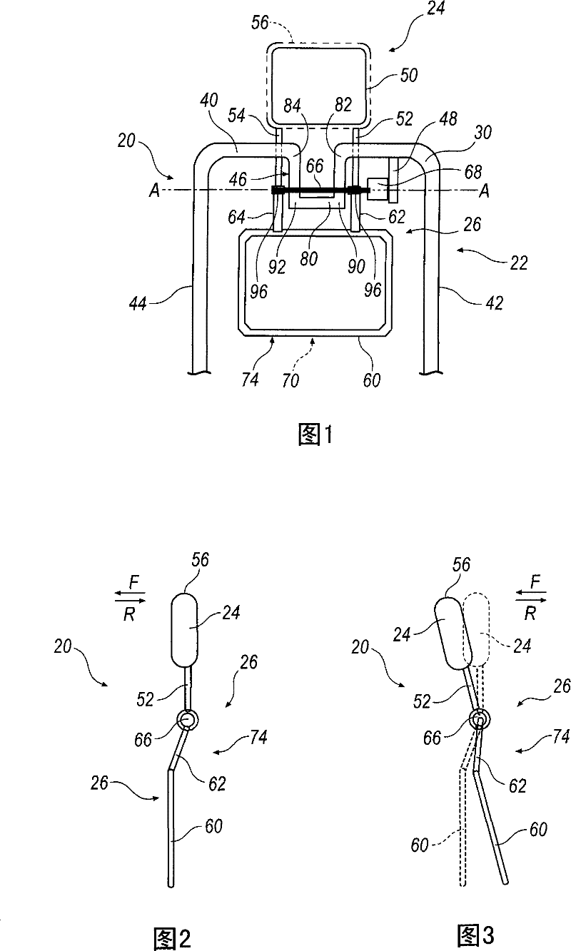
[0029] Figure 1-Figure 3 An active head restraint system 20 is shown. System 20 includes seat back 22 , head restraint 24 , and head restraint control system 26 . The seat back 22 includes a seat back frame 30 attached to a seat bottom (not shown), and a seat back outer cover (not shown). The seat back frame 30 includes a horizontal member 40 , a first vertical member 42 , a second vertical member 44 , a headrest connection portion 46 , and a speed reducer connection portion 48 . The headrest 24 includes a structural portion 50 , a first link 52 , a second link 54 , and a headrest outer cover 56 .

[0030] The head restraint control system 26 includes a chest full member or back plate 60, a first back plate link 62, a second back plate link 64, an interconnect 66 having an axis A-A, a rotational damper or deceleration device 68, and Latch or lock mechanism 70 . In the illustrated embodiment, the head restraint control system 26 is located within an outer seat back cover o...


PUM


Abstract

An apparatus includes a seat back having an outer surface that selectively contacts a seat occupant and a head restraint extending from the seat back that has a head restraint portion that selectively contacts the seat occupant. The head restraint portion is moveable between a forward position and a rearward position. The apparatus also includes a head restraint control assembly having an actuator, a lock mechanism, and a lock mechanism resetting device. The actuator transfers an actuation force to the head restraint portion for initiating movement of the head restraint portion from the rearward position to the forward position. The lock mechanism selectively restrains the headrest portion from moving from the forward position to the rearward position. The lock mechanism will restrain theheadrest portion from moving from the forward position to the rearward position in a first actuation event and selectively reset by action of the lock mechanism resetting device in order to restrain the headrest portion from moving from the forward position to the rearward position in a second actuation event. The lock mechanism resetting device will reset the lock mechanism without manipulation from an outside source.

Description

technical field [0001] The present invention generally relates to head restraint assemblies in automobiles. Background technique [0002] Every seat in a car typically includes a headrest. These head restraints typically extend vertically from the seat back and prevent hyperextension of the neck. A typical sensor-actuated head restraint has a mechanism for moving the head restraint forward during an impact, such a mechanism including a stored energy source and a trigger. The stored energy source may be a compression spring for moving the head restraint to the desired position, or an energy source of pyrotechnic energy (chemical energy) or electrical energy. The trigger may be a latch or an electric device that initiates movement of the head restraint. However, such systems build on complexity and provide additional failure modes for the system. [0003] Some head restraints can move forward during a crash, but return to the rearward position when required to stay in the...

Claims


Application Information

Patent Timeline
Patent Type & Authority Patents(China)
IPC IPC(8): B60N2/433
CPCB60N2/4864B60N2/4885B60N2/4838B60N2/838B60N2/888B60N2/865
Inventor A·曼加拉·M·贾亚苏里亚詹姆士·亚当斯迈克尔·拉西克马克·李普曼兹比格涅夫·奥泽尔斯齐
Owner FORD GLOBAL TECH LLC
Why Eureka
Try Eureka