
Ozone generator with modular structural discharging unit

A technology of ozone generator and discharge module, which is applied in the direction of ozone preparation, etc., can solve the problems that the output of ozone equipment cannot be adjusted according to actual needs, it is not easy to produce, install and maintain, and it takes a lot of time, so as to shorten machine downtime and reduce Maintenance work and labor cost, effect of increasing ozone production

Active Publication Date: 2010-12-08
FUJIAN NEWLAND ENTECH CO LTD
View PDF2 Cites 0 Cited by
  • Summary
  • Abstract
  • Description
  • Claims
  • Application Information

AI Technical Summary

Problems solved by technology

All the internal electrodes in the ozone generator are connected separately. When the number of electrodes is large, it takes a lot of time to connect all the internal electrodes separately, and the connector needs to be very careful to avoid missing connections or repeated connections of the same electrode. , especially when the number of electrodes reaches hundreds or even thousands, the existing ozone generators containing a large number of electrodes are large in size, the ozone output of a single device is small, and it is not easy to produce, install and maintain, and all The discharge units are all supplied with uniform power supply and oxygen supply. The output of the ozone equipment cannot be adjusted according to the actual needs, and the ozone generator needs to be shut down when the discharge unit needs to be replaced and other maintenance work. Ozone generator with large size, adjustable ozone output, no need to stop for maintenance, and easy to produce, install and maintain

Method used


Image

  • Ozone generator with modular structural discharging unit
  • Ozone generator with modular structural discharging unit
  • Ozone generator with modular structural discharging unit

Examples


Embodiment Construction

[0024] An embodiment of the present invention will be specifically described below in conjunction with the accompanying drawings.

[0025] Such as Figure 1~5 Shown is an embodiment of the ozone generator with the modular structure of the discharge unit of the present invention.

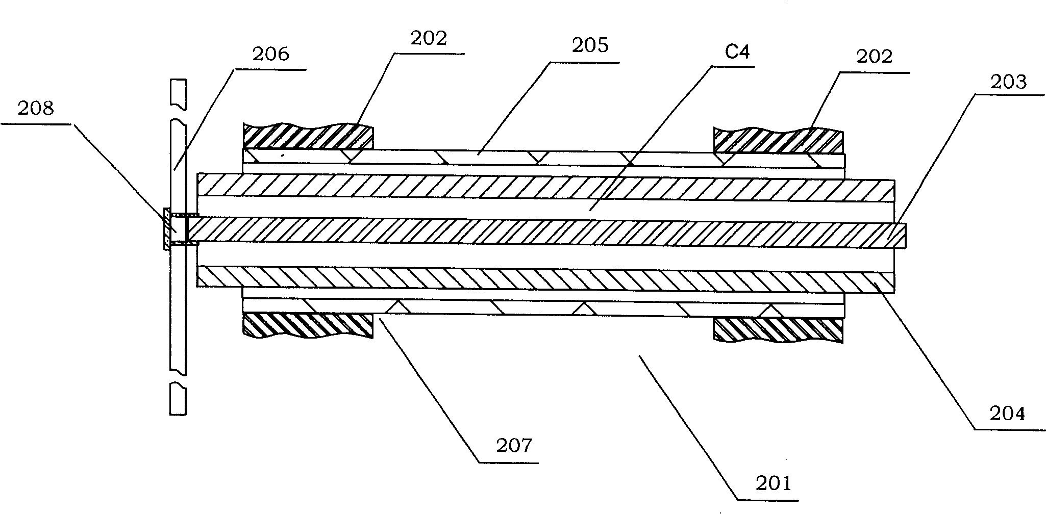
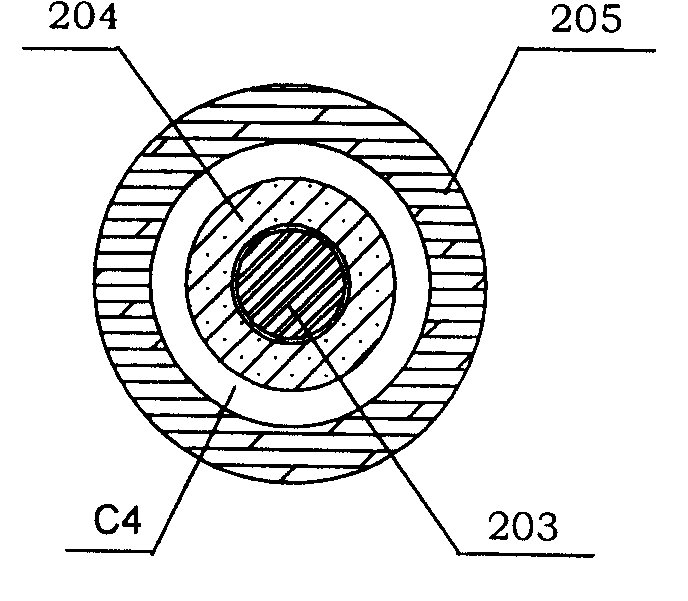
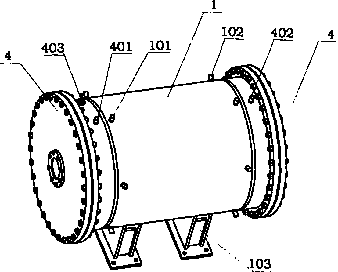
[0026] In this embodiment, the ozone generator includes a discharge chamber C1, an oxygen chamber C2 at both ends of the discharge chamber C1, and an ozone chamber C3. The discharge chamber C1 includes at least one discharge module 2 and two discharge module fixing plates 3 for fixing the discharge module, and the outside of the two discharge module fixing plates 3 are sealed by respective end caps 4 to form two cavities C2 and C3 They are used as oxygen chamber and ozone chamber respectively. The discharge chamber C1 is sealed by the outer wall to form a closed cavity as the cooling cavity 1 , and the corresponding positions of the two discharge module fixing plates 3 have several pairs of through...


PUM


Abstract

The invention provides an ozonizer with modular structure of a discharge unit, which includes a discharge chamber, an oxygen cavity chamber and an ozone cavity chamber; the discharge chamber includes at least one discharge module and two fixing discs used for fixing the discharge modules, and the oxygen cavity chamber and the ozone cavity chamber are arranged at the outside of the fixing discs ofthe two discharge modules; each discharge module includes a plurality of discharge units and two discharge unit fixing plates that are arranged at the two ends of the discharge unit, the discharge module is arranged on the two fixing discs of the discharge modules by the discharge unit fixing plates at the both ends; each discharge unit includes an internal electrode, an insulation sleeve and an external electrode that are sheathed together from inside to outside according to the sequence of the internal electrode, the insulation sleeve and the external electrode, an air gap is kept between the internal electrode and the external electrode, an electric connection is formed between the internal electrodes and between the external electrodes inside each discharge module. The ozonizer adopting the structure includes a lot of electrodes and has high unit set output, small volume but is easy to manufacture, install and maintain.

Description

Technical field: [0001] The invention belongs to the field of ozone generators, in particular to a large-scale ozone generator with a large number of electrodes. technical background: [0002] Existing large-scale discharge method for preparing ozone, the air-gap corona discharge ozone generator generally puts dozens or even hundreds or more sets of dielectric tubes and discharge rods (i.e. inner electrodes) installed in concentric circles. In a discharge chamber made of a metal cylinder, the high-voltage electrode is used as the inner electrode, and the outer shell of the discharge chamber is used as the outer electrode. All the internal electrodes in the ozone generator are connected separately. When the number of electrodes is large, it takes a lot of time to connect all the internal electrodes separately, and the connector needs to be very careful to avoid missing connections or repeated connections of the same electrode. , especially when the number of electrodes reach...

Claims


Application Information

Patent Timeline
Patent Type & Authority Patents(China)
IPC IPC(8): C01B13/11
Inventor 陈健王涛
Owner FUJIAN NEWLAND ENTECH CO LTD
Learn More