Spiral cylindric discharging unit for ozone generator

An ozone generator and discharge unit technology, applied in the field of ozone generators, can solve the problems of small discharge specific surface area of ​​ozone generators, high installation and maintenance costs, increased floor space, etc., to reduce equipment investment and maintenance costs, easy to use. Maintenance and space saving effect

Active Publication Date: 2014-01-08
FUJIAN NEWLAND ENTECH CO LTD
View PDF3 Cites 0 Cited by
  • Summary
  • Abstract
  • Description
  • Claims
  • Application Information

AI Technical Summary

Problems solved by technology

But its disadvantage is that each discharge unit is a separate set of concentrically installed high-voltage electrodes, insulating tubes and ground electrodes. The single discharge unit produces low ozone, and the discharge specific surface area of ​​the entire ozone generator is small, resulting in The ozone production rate is reduced, resulting in a large-scale ozone generator containing a large number of the above-mentioned discharge units. In addition, due to the use of materials such as stainless steel, glass or ceramics, the equipment is bulky, the floor area is increased, and the investment cost of the entire equipment is also high. , and the complex structure
Moreover, the high-voltage electrode, insulating tube and ground electrode are concentric, so the requirements for installation are also high, and the insulating tube is prone to damage, resulting in high installation and maintenance costs. Therefore, it is necessary to overcome the above shortcomings and have a large specific surface area. , A single discharge unit with high ozone output, simple structure, small footprint, low maintenance and operation cost, easy to manufacture and install the discharge unit

Method used


Image

  • Spiral cylindric discharging unit for ozone generator
  • Spiral cylindric discharging unit for ozone generator
  • Spiral cylindric discharging unit for ozone generator

Examples


Embodiment 1

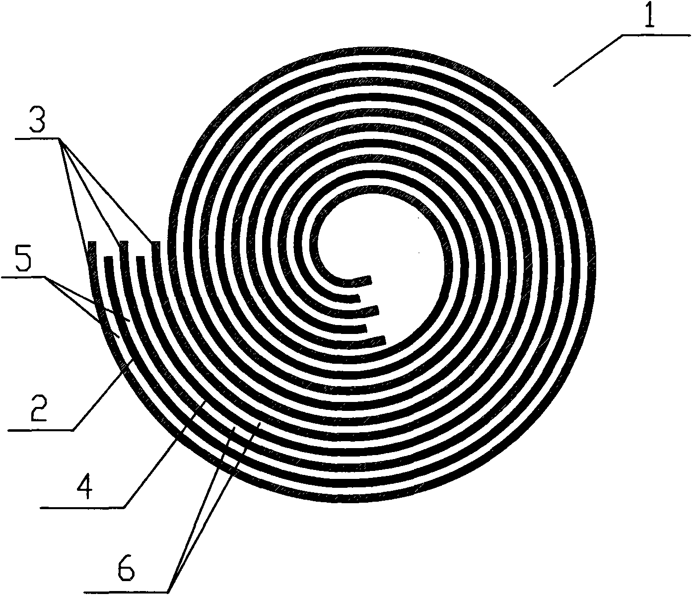
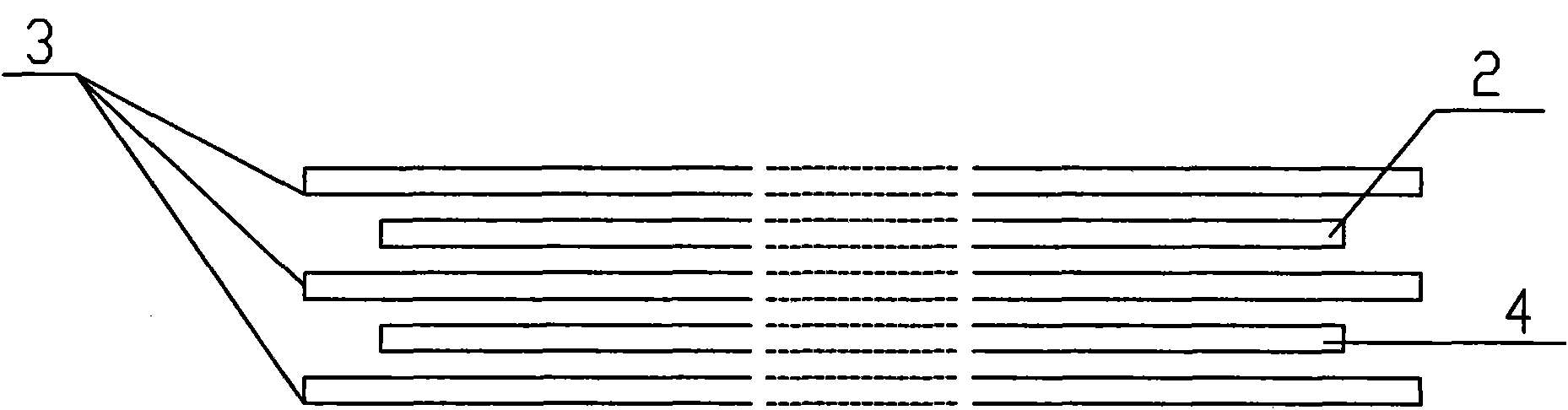
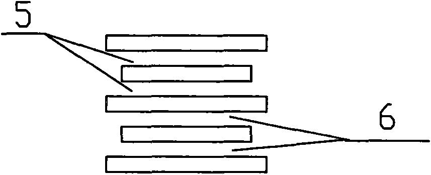
[0029] Such as Figure 1-3 As shown, the spiral cylindrical discharge unit 1 for the ozone generator is composed of a group of film-shaped and rollable ground electrodes 2, insulating layers 3 and high-voltage electrodes 4, and the number is not less than one. One edge is wound into several turns of a spiral cylinder, in which the high-voltage electrode 4 and the ground electrode 2 are separated by the insulating layer 3, and there are gaps between the ground electrode 2 and the insulating layer 3, and between the insulating layer 3 and the high-voltage electrode 4 5 and 6. The spiral cylindrical discharge unit 1 in this embodiment is formed by stacking one layer of ground electrode 2 , three layers of insulating layers 3 and one layer of high voltage electrode 4 . The edge of the insulating layer 3 protrudes beyond the ground electrode 2 and the high voltage electrode 4 . The sizes of the gaps 5 and 6 are between 0.05mm and 0.4mm respectively.

Embodiment 2

[0031] Such as Figure 4 As shown, different from Embodiment 1, in Embodiment 2, the spiral cylindrical discharge cell also includes an axis 7, and the stacked ground electrode 2, insulating layer 3 and high voltage electrode 4 take the axis 7 as the axis 7. The center is wound around the axis 7 as a whole to form a spiral cylinder. The shaft 7 is in the shape of a hollow tube. In practical applications, water or other cooling media can be passed through the tube to achieve good heat dissipation. It is also possible to electrically connect the shaft to the high voltage electrodes.

[0032] In order to facilitate identification, the number of helical turns of the helical cylindrical discharge unit shown in the schematic diagram of the embodiment of this specification is relatively small, which can be increased as required in practical applications. In the figure, there is one high-voltage electrode and one ground electrode, and three insulating layers. In practical applicatio...


PUM

PropertyMeasurementUnit
porosityaaaaaaaaaa

Abstract

The invention discloses a spiral cylindric discharging unit for an ozone generator, characterized by that: a set of flexible ground electrodes, insulation layers and high voltage electrodes with the respective quality of no less than one are stacked up and integrally kinkled to form the spiral cylindric shape, wherein, the high voltage electrodes and the ground electrodes are separated by the insulation layers, gaps exist between the ground electrodes and the insulation layers and between the insulation layers and the high voltage electrodes. The spiral cylindric discharging unit can be applied to various ozone generators with observably improving the ozone productivity of each discharging unit and reducing the cost.

Description

Technical field: [0001] The invention belongs to the field of ozone generators and relates to a discharge unit of the ozone generator. Background technique: [0002] The discharge unit of the existing large-scale ozone generator generally includes a concentrically installed high-voltage electrode, an insulating tube and a ground electrode, and the sequence from the inside to the outside is the high-voltage electrode, the insulating tube and the ground electrode. Generally, ceramic-coated glass tubes are used as insulating tubes, and stainless steel tubes are used as electrode materials. Dry and purified air or oxygen passes through the discharge gap between the electrodes and the insulating layer. After electrification, ozone is generated in the gap. But its disadvantage is that each discharge unit is a separate set of concentrically installed high-voltage electrodes, insulating tubes and ground electrodes. The single discharge unit produces low ozone, and the discharge spec...

Claims


Application Information

Patent Timeline
Patent Type & Authority Patents(China)
IPC IPC(8): C01B13/11
Inventor 陈健王涛
Owner FUJIAN NEWLAND ENTECH CO LTD
Why Eureka
Try Eureka