Large-sized ozone gas generator

A gas generator and ozone technology, applied in the direction of ozone preparation, etc., can solve problems such as hindering heat dissipation, reducing ozone efficiency, electrode damage, etc., and achieve the effects of promoting mutual diffusion, good cooling effect, and high ozone production

Inactive Publication Date: 2018-07-24
SUZHOU BLUE KING MACHINE TOOL TECH CO LTD +1
View PDF0 Cites 0 Cited by
  • Summary
  • Abstract
  • Description
  • Claims
  • Application Information

AI Technical Summary

Problems solved by technology

[0002] As we all know: large-scale ozone generators mainly use water cooling to cool the generator, that is, tap water or circulating tap water is passed into the barrel of the generator. It is known from fluid mechanics that fluids have a certain viscosity, and the flow in the pipeline It is carried out in layers, that is: turbulent flow layer and laminar flow layer, wherein: the laminar flow layer is located within a certain range of the inner wall of the pipeline or the surface of obstacles in the pipeline, and the fluid flow in this range is in a certain stable state, which is different from other parts. The energy exchanged by the fluid is the least. Obviously: the outer circular surface of a large number of stainless steel tubes set in the generator cylinder as the external electrode is the formation area of ​​the laminar layer, and the energy exchange effect with the surrounding fluid is poor, which reduces the cooling effect to a certain extent. Cause electrode damage and reduce the efficiency of ozone production. In addition, because the cooling water generally contains a certain amount of impurities and metal calcium and magnesium ions, after a certain period of time, it is easy to form scale on the outer surface of the stainless steel tube as the external electrode, which will Seriously hinder the heat dissipation, not only aggravate the loss or damage of the electrode, reduce the production efficiency of ozone, and even lead to the scrapping of the entire generator in severe cases

Method used


Image

  • Large-sized ozone gas generator

Examples


Embodiment Construction

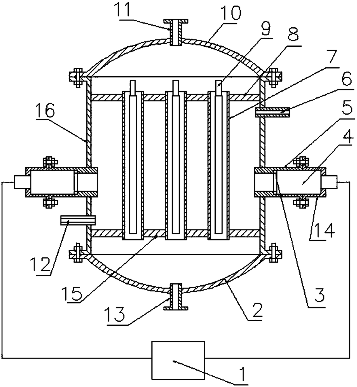
[0009] A large-scale ozone gas generator, which includes an ultrasonic generating circuit module (1), a lower head (2), a sealing ring (3), an ultrasonic transducer (4), a short round tube (5), and a water outlet joint (6), stainless steel pipe (7), upper blocking plate (8), inner electrode (9), upper head (10), air inlet joint (11), water inlet joint (12), air outlet joint (13 ), a fixing device (14), a lower blocking plate (15), and a barrel body (16). An upper blocking plate (8) and a lower blocking plate (15) are respectively arranged at the upper and lower ports of the barrel body (16), and several The stainless steel tube (7) penetrates the upper blocking plate (8) and the lower blocking plate (15) and is welded together with the upper blocking plate (8) and the lower blocking plate (15) at the end, and is set in each stainless steel tube (7) An inner electrode (9), the inner electrode (9) and the stainless steel pipe (7) should be reliably fixed, and an upper head ( 10...


PUM


Abstract

The invention relates to a large-sized ozone gas generator. According to the generator, a drum body is provided with one or a plurality of short circular tubes, the short circular tubes are communicated with the interior of the drum body, the short circular tubes are internally provided with ultrasonic transducers, the vibration end parts of the ultrasonic transducers are in contact with cooling water, seal rings are used for sealing between the inner ends of the ultrasonic transducers and the short circular tubes, and the ultrasonic transducers are fixed in the short circular tubes by using fixing devices. The large-sized ozone gas generator has the advantages that the cooling effect is relatively good, the ozone yield is relatively high, and the service life is relatively long.

Description

technical field [0001] The invention relates to an ozone device, in particular to an ozone generator, and belongs to the technical field of ozone generators. Background technique [0002] As we all know: large-scale ozone generators mainly use water cooling to cool the generator, that is, tap water or circulating tap water is passed into the barrel of the generator. It is known from fluid mechanics that fluids have a certain viscosity, and the flow in the pipeline It is carried out in layers, that is: turbulent flow layer and laminar flow layer, wherein: the laminar flow layer is located within a certain range of the inner wall of the pipeline or the surface of obstacles in the pipeline, and the fluid flow in this range is in a certain stable state, which is different from other parts. The energy exchanged by the fluid is the least. Obviously: the outer circular surface of a large number of stainless steel tubes set in the generator cylinder as the external electrode is the ...

Claims


Application Information

Patent Timeline
Patent Type & Authority Applications(China)
IPC IPC(8): C01B13/10
CPCC01B13/10
Inventor 黄振寰黄运新
Owner SUZHOU BLUE KING MACHINE TOOL TECH CO LTD
Why Eureka
Try Eureka