Staple fiber delivery mechanism for melt blown nonwoven cloth processor

A melt-blown non-woven fabric and conveying mechanism technology, applied in non-woven fabrics, textiles and papermaking, etc., can solve the problem of large price constraints, loss of market competitiveness of the final product, and limited disclosure of melt-blown non-woven fabric equipment, etc. problem, to achieve a reasonable effect of the design

Inactive Publication Date: 2008-07-30
常熟市伟成非织造成套设备有限公司
View PDF5 Cites 10 Cited by
  • Summary
  • Abstract
  • Description
  • Claims
  • Application Information

AI Technical Summary

Problems solved by technology

However, there is no successful self-made equipment for processing melt-blown non-woven fabrics in my country so far, and because foreign companies have not exported equipment in order to ensure the advantages of melt-blown non-woven products in the Chinese market, even in the literature such as US Patent US5508102 , US4931355, US4755178, US4623576, US4604313, etc. have very limited disclosure of complete sets of melt-blown non-woven equipment. Therefore, the melt-blown non-woven fabrics used by clothing and bedding manufacturers in my country can only rely on imports. Affected by price constraints, it loses the market competitiveness of the final product

Method used


Image

  • Staple fiber delivery mechanism for melt blown nonwoven cloth processor
  • Staple fiber delivery mechanism for melt blown nonwoven cloth processor
  • Staple fiber delivery mechanism for melt blown nonwoven cloth processor

Examples


Embodiment Construction

[0019] In order to enable examiners, especially the public, to fully understand the technical essence of the present invention, a detailed description is given in specific implementation modes in conjunction with the accompanying drawings, but all descriptions of the embodiments do not constitute limitations on the technical solutions of the present invention.

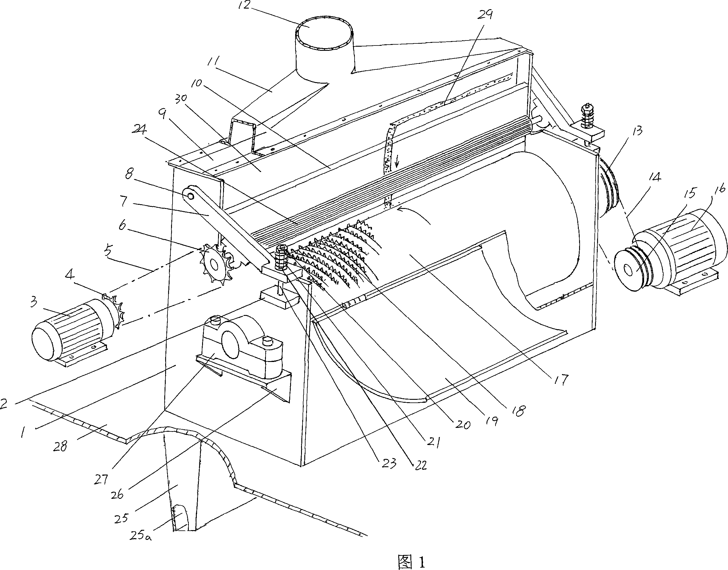
[0020] Please see Fig. 1, as the box body 1 of staple fiber conveying mechanism is fixedly installed on the working platform 28, the box wall on both sides of the longitudinal direction of this box body 1, that is, the left and right box walls of the position state shown in the figure generally constitutes For symmetry, the roller shafts at the two ends of the combing roller 17 are each pivoted on the two sides of the box wall through the bearing seat 27, and a pair of bearing seats 27 are fixed on the shaft seat bracket 26 with bolts or other similar fixtures. Above, the shaft seat bracket 26 is fixed on the outer wall...


PUM


Abstract

A short fiber transportation mechanism of a melting blow nonwoven cloth processing machine belongs to the nonwoven machinery technology field, comprising a box body, a wool carding roller, an airflow groove, a backup plate and a cotton driving roller. The mechanism is characterized in that an airflow cover is extendedly arranged on the upper part of the airflow groove, the top center of the airflow cover is funneled into an air inlet, the lower part of the airflow groove extends to the lower part of a working platform and forms a further flatly shrunk cotton spraying tube; the cotton driving roller is connected onto the outer wall of the lengthwise corresponding box wall of the box body; the carding roller is inserted into the airflow groove. The mechanism has the advantages that the cotton driving roller can be adapted to driving thickness-varied short fiber cotton blankets; the airflow carrying short fiber can be guaranteed to be sprayed out from the cotton spraying tube which extends to the lower part of the working platform and corresponds to a melted extrusion structure, and brought together with the hot melted fibers extruded by the melted extrusion machine to conglutinate into a melting blow fiber layer.

Description

technical field [0001] The invention belongs to the technical field of non-woven machinery, and specifically relates to a short fiber conveying mechanism of a melt-blown non-woven fabric processing machine, which is used to cooperate with the melt-extruding mechanism and the composite forming mechanism of the melt-blown non-woven fabric processing machine to process Meltblown nonwoven finished product. Background technique [0002] Melt-blown non-woven fabric is the first non-woven product developed abroad. It consists of upper and lower layers of thin, porous non-woven fiber cloth layers and a non-woven fiber cloth layer between the non-woven fiber cloth layers. It is composed of a fiber layer containing thermally melt-bonded fibers (customarily called a melt-blown fiber layer), and is in the form of a sandwich in terms of structure. This kind of melt-blown non-woven fabric product has excellent compression deformation when compressed in the thickness direction and recover...

Claims


Application Information

Patent Timeline
IPC IPC(8): D04H5/06
Inventor 王卫成
Owner 常熟市伟成非织造成套设备有限公司
Why Eureka
Try Eureka