Method and structure for inhibiting dynamic response time of lens focusing drive structure

A technology of dynamic response and drive structure, applied in vibration suppression adjustment, installation, optics, etc., can solve the problems of jitter, long time, no improvement of dynamic response time, etc., to improve performance, save power, and improve lens quality. Effect

Inactive Publication Date: 2008-07-30
TDK TAIWAN
View PDF0 Cites 13 Cited by
  • Summary
  • Abstract
  • Description
  • Claims
  • Application Information

AI Technical Summary

Problems solved by technology

[0004] However, as long as the lens has the function of auto focus, it will shake when the focus moves to the positioning stop, and then slowly reaches a steady state. This period of time from static movement to stop is called dynamic response time (Response Time) ),like figure 2 As shown, it is a schematic diagram of a dynamic response waveform for detecting a known focus driving structure, which is represented by figure 2 It can be seen that it takes 1.34035 seconds to reach a steady state, which is quite a long time
[0005] Since this dynamic response time will affect the length of time for the lens module to focus, it will have a great impact on the quality of the lens module, especially the length of time required for focusing. The longer the dynamic response time, the longer the required focusing time, so It is necessary to shorten the dynamic response time in order to effectively improve the time required for focusing, but there is currently no literature or technology to improve this dynamic response time

Method used


Image

  • Method and structure for inhibiting dynamic response time of lens focusing drive structure
  • Method and structure for inhibiting dynamic response time of lens focusing drive structure
  • Method and structure for inhibiting dynamic response time of lens focusing drive structure

Examples


Embodiment Construction

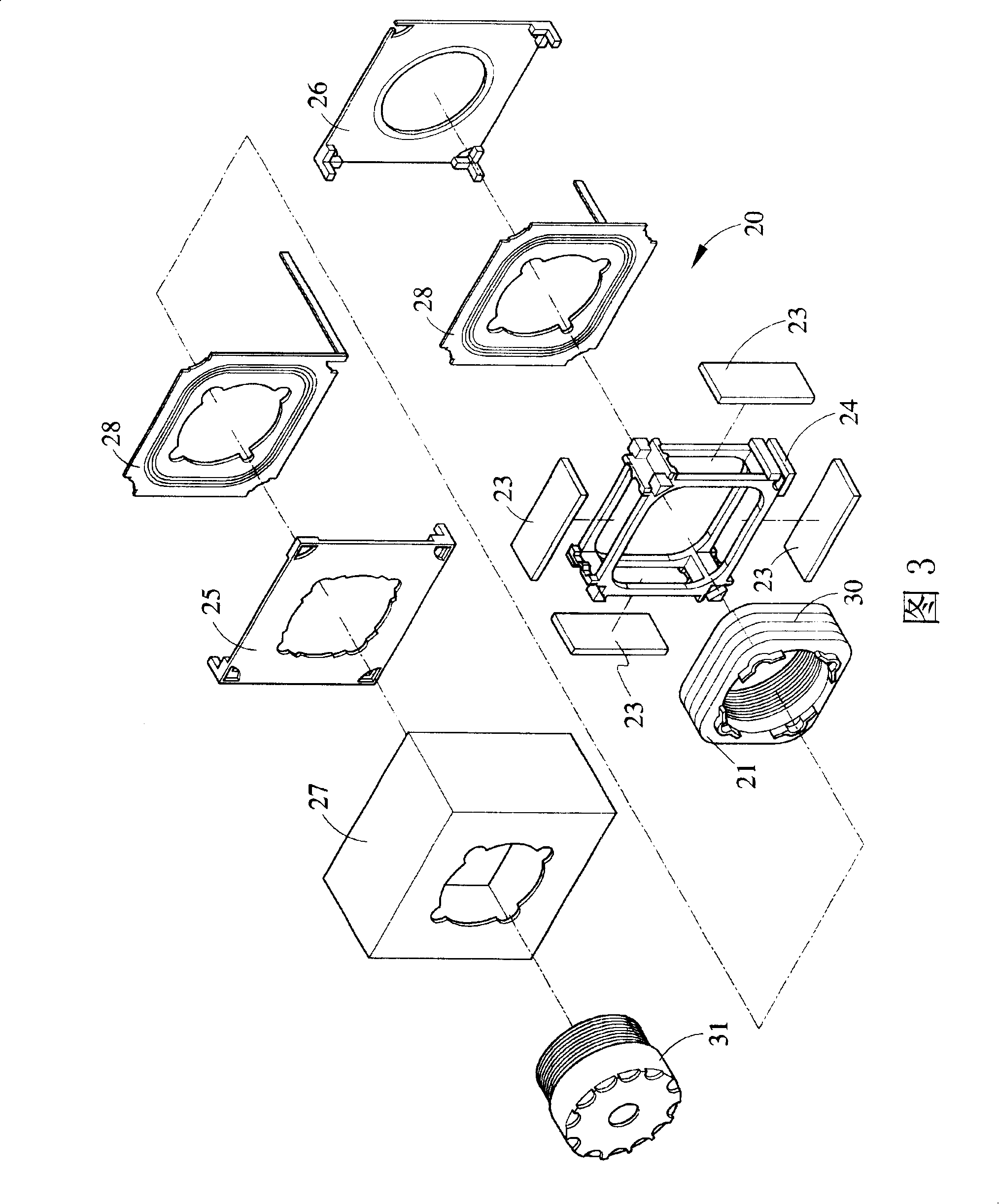
[0042] The present invention is mainly aimed at suppressing the dynamic response time (Response Time) when the lens is focused, so a lens focusing drive structure is used as an embodiment description, as shown in Figure 3, which is a three-dimensional exploded view of a lens focusing drive structure, and Figure 4A It is the perspective view of the bottom surface of Fig. 3 (the lens is omitted), Figure 4B for Figure 4A A partially enlarged schematic diagram of the lens focus driving structure 20 includes a base 21 , several magnetic parts 23 , a frame 24 , a front cover 25 , a bottom cover 26 , a housing 27 and several elastic components 28 . Wherein the base 21 has a coil 30 and a lens 31, the base 21 is arranged in the center of the frame 24, the lens 31 is installed in the center of the base 21, the coil 30 is wrapped around the base 21, the The magnetic part 23 is disposed on the periphery of the frame 24 so that it is located just outside the coil 30 and maintains a fi...


PUM


Abstract

The invention discloses a method for inhibiting dynamic response time of a lens focusing driving structure and an inhibiting structure thereof. The inhibiting structure comprises a mobile mechanism, an immobile mechanism and at least a vibration absorption component. The mobile mechanism at least comprises a pedestal provided with a lens in the center and circumference coated with a coil. The immobile mechanism at least comprises a frame, a front cover and a bottom cover. A plurality of magnetic components are embedded around the frame, and the center of the frame can hold the mobile mechanism. The vibration absorption component is connected between the mobile mechanism and the immobile mechanism and used for absorbing the vibration generated when the mobile mechanism is moved from the focusing position to the positioning position. The invention can inhibit the dynamic response time of the mobile mechanism reaching steady state.

Description

technical field [0001] The present invention relates to a lens focusing drive response time (Response Time) suppression method and structure, in particular to a structure capable of suppressing the response time of micro-lens focus drive, reducing the jitter produced by lens focus movement, and quickly reaching a steady state . Background technique [0002] With the advancement of technology, the volume of digital cameras has shrunk quite small, and most of the current mobile phones have the functions of digital cameras. These are all due to the modularization and miniaturization of camera lenses, and there are many Various types of autofocus drive structure, the most commonly used one is the voice coil motor (VCM), because of its small size, low power consumption, precise actuation displacement and low price, it is suitable as a short-term driver for micro-lens autofocus. distance drive. [0003] like figure 1 As shown, it is a three-dimensional exploded schematic diagra...

Claims


Application Information

Patent Timeline
Patent Type & Authority Applications(China)
IPC IPC(8): G02B7/04G02B7/09F16F15/00
Inventor 吴富源范肇婷
Owner TDK TAIWAN
Why Eureka
Try Eureka