Hair removing system

A hair removal and hair removal technology, applied in medical science, surgery, parts of surgical instruments, etc., can solve the problem that no known equipment can provide a sufficiently high speed

Inactive Publication Date: 2008-07-30
KONINKLIJKE PHILIPS ELECTRONICS NV
View PDF0 Cites 15 Cited by
  • Summary
  • Abstract
  • Description
  • Claims
  • Application Information

AI Technical Summary

Problems solved by technology

Since human hair is a sparse object sparsely distributed on the skin, no known devi...

Method used


Image

  • Hair removing system
  • Hair removing system
  • Hair removing system

Examples


Embodiment Construction

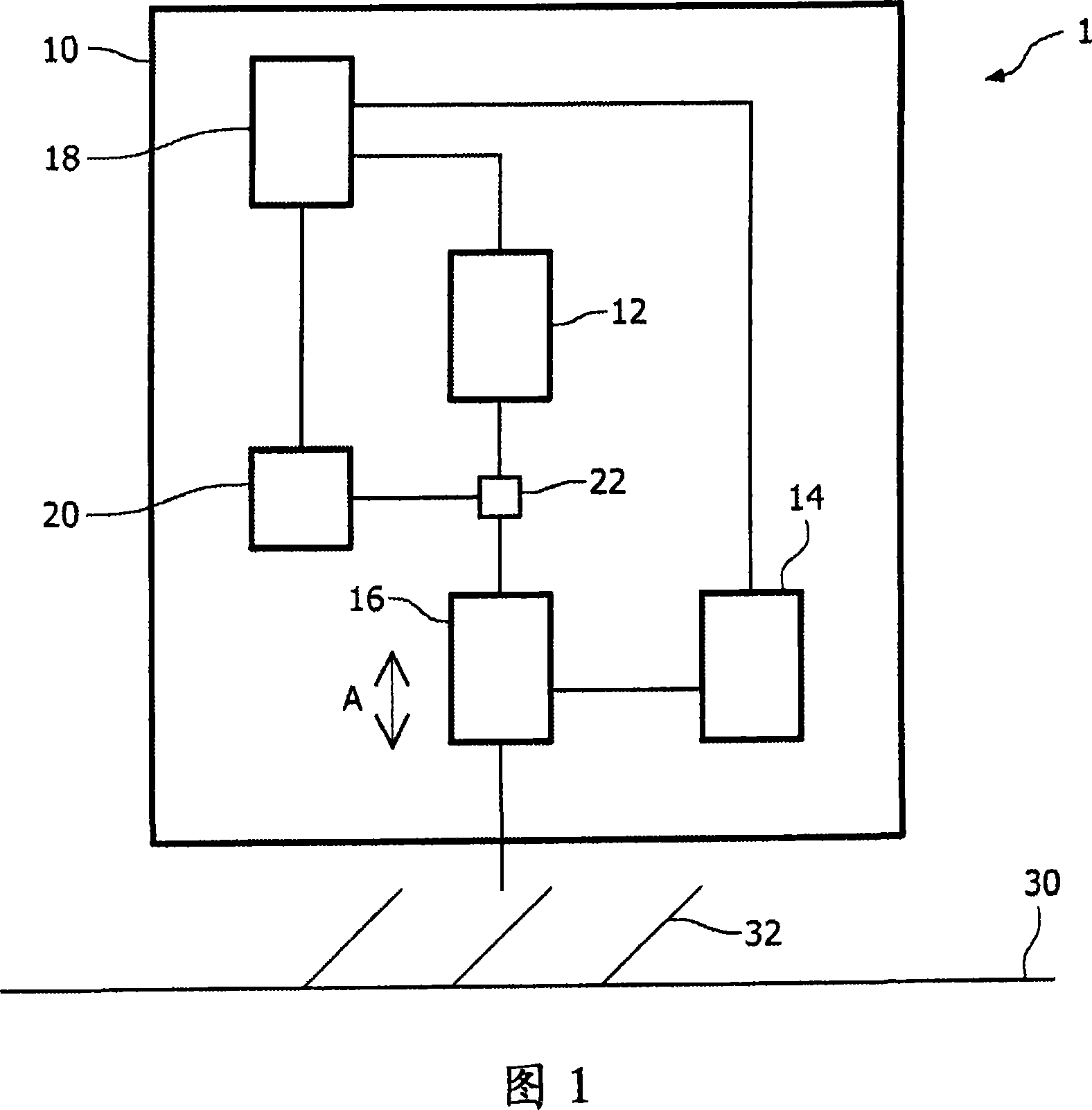
[0035] Figure 1 shows very schematically a system according to the invention. Here, the system 1 comprises a housing 10 with a first image sensor 12 , a second image sensor 14 with an adjustable lens 16 , a control unit 18 , a hair removal device 20 and an optical coupler 22 . In the above, the separate movable lens 16 and optical coupler 22 are optional as will be further explained.

[0036] Also shown is skin 30 with hair 32 to be removed.

[0037] The housing 10 of the system 1 as shown comprises only those parts which are relevant for the present invention. Obviously, additional parts may be present but not shown, such as power units, optical windows, etc.

[0038] The first image sensor 12 may include, for example, a CCD camera, a CMOS device, and the like. The second image sensor 14 is coupled to an adjustable lens 16 and may include a scanning unit.

[0039] Both image sensors 12 and 14 are coupled to a control unit 18 which is constructed and arranged to resolve ha...


PUM


Abstract

The invention relates to a system and method for removing hair. The system comprises a hair detection device and a hair-removing device (20). Since 3D information on hairs (32) is required, but due to the very dispersed presence of, e.g., human hairs (32) on skin (30), known detection devices are too slow, the invention provides a combination of two image sensors. A first image sensor (12) produces a first image, based on which a selected part is imaged with a second image sensor (14) that provides the required 3D position information with which the hair-removing device (20) can remove the hair. Thus, optimum use may be made of both fast but less accurate image sensors, such as (2D) CCDs or CMOS sensors, and accurate but slow sensors such as 3D scanning sensors.

Description

technical field [0001] The present invention relates to a hair removal system, in particular to a hair removal system comprising a hair detection device and a hair removal device operatively coupled to the hair detection device, wherein the hair detection device comprises: an imaging device comprising a first image sensor, configured and arranged to detect an image of the portion of skin to be treated; and a control unit constructed and arranged to resolve hair on the portion of skin in the image and operatively coupled to the hair removal device to control operation thereof. Background technique [0002] WO 0 / 62700 also relates to a hair removal device and discloses a device with a laser source, an adjustable beam manipulator, an image sensor and a control unit for determining the position and orientation of the hair on the skin. The image sensor includes a CCD or a CMOS sensor. [0003] Problems with known devices relate to determining the position and / or orientation of t...

Claims


Application Information

Patent Timeline
IPC IPC(8): A61B18/20
CPCA61B18/203A61B18/20A61B2018/00452A61B2018/00476A61B2018/00904
Inventor B·L·G·巴克R·A·M·范哈尔R·维哈根
Owner KONINKLIJKE PHILIPS ELECTRONICS NV
Why Eureka
Try Eureka