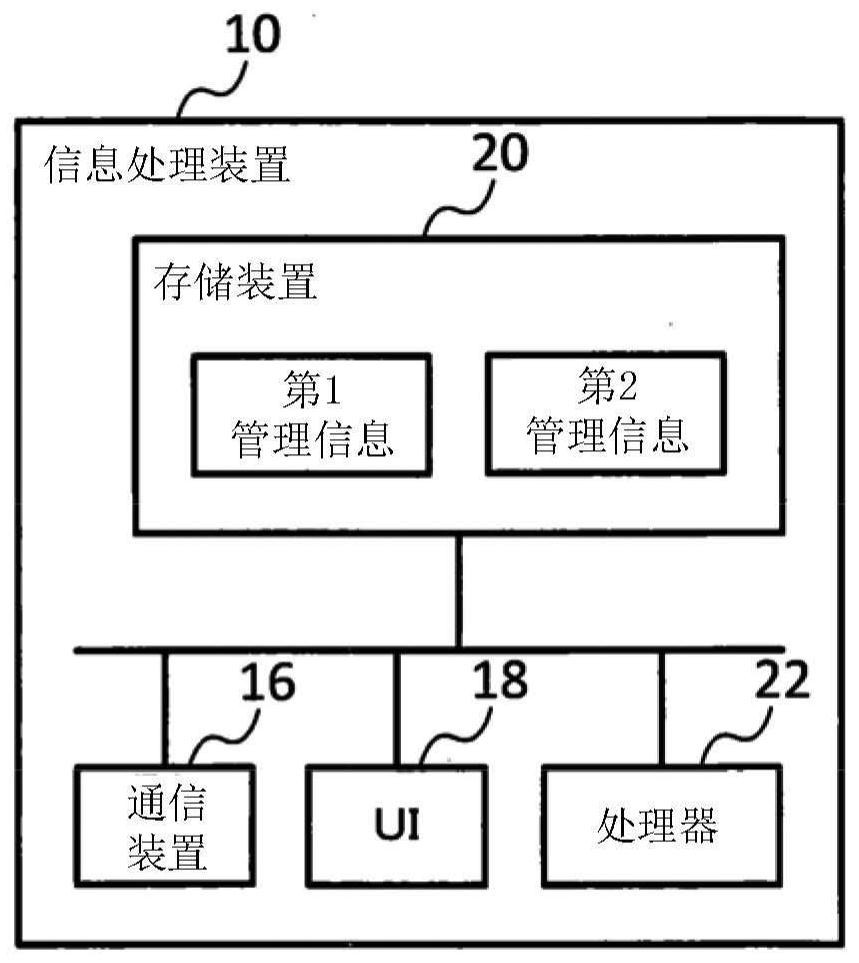
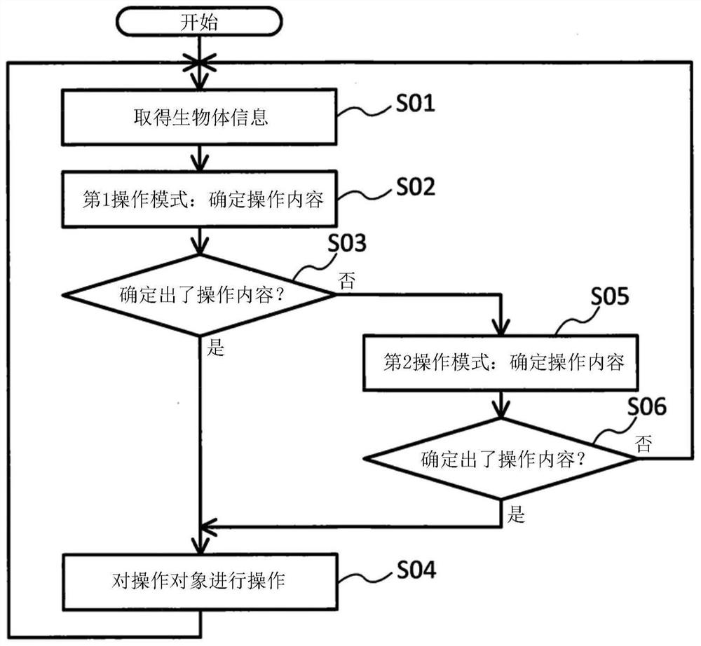
Information processing device and computer readable medium
An information processing device and processor technology, applied in computer control, computer components, calculation, etc., can solve problems such as inability to operate biological information on operating objects
- Summary
- Abstract
- Description
- Claims
- Application Information
AI Technical Summary
Problems solved by technology
Method used
Image
Examples
Embodiment 1
[0146] Below, refer to Figure 8 Example 1 will be described. Figure 8 A graph representing temporal changes in biological information is shown in . The horizontal axis represents time, and the vertical axis represents amplitude.
[0147] In Embodiment 1, in the first operation mode, the processor 22 operates the operation object according to the comparison result between the user's biometric information and the first threshold. In addition, in the second operation mode, the processor 22 operates the operation object according to the comparison result between the biometric information of the user and the second threshold different from the first threshold. The second threshold is a value smaller than the first threshold. Hereinafter, Example 1 will be described in detail.
[0148] Figure 8 The waveform 24 in the figure is an example of the first reference biometric information associated with the operation information indicating a certain operation content X. Each peak...
Embodiment 2
[0158] Below, refer to Figure 9 Example 2 will be described. Figure 9 An example of a waveform represented by biological information is shown in .
[0159] In Embodiment 2, in the second operation mode, the processor 22 makes the sensitivity of the sensor for measuring the user's biological information (for example, the biological information measuring device 12 ) higher than that in the first operation mode. That is, the processor 22 makes the detection sensitivity in the second operation mode higher than the detection sensitivity in the first operation mode.
[0160] The waveform 28 is a waveform represented by biological information measured in the first operation mode. The waveform 30 is a waveform represented by biological information measured in the second operation mode. In the second operation mode, the detection sensitivity is higher than that in the first operation mode, so the amplitude of the waveform 30 is larger than the amplitude of the waveform 28 by ΔS. ...
Embodiment 3
[0166] Below, refer to Figure 10 Example 3 will be described. Figure 10 A graph representing temporal changes in biological information is shown in . The horizontal axis represents time, and the vertical axis represents amplitude.
[0167] The waveform 32 is an example of first reference biometric information associated with operation information indicating a certain operation content X. FIG. The waveform 32 is a waveform having three peaks (for example, peaks 32a, 32b, and 32c). Peaks 32a, 32b, 32c characterize waveform 32 .
[0168] The waveform 34 is biological information measured from the user. The waveform 34 is a waveform having two peaks (for example, peaks 34b, 34c). Peaks 34b, 34c characterize waveform 34 .
[0169] For example, waveforms 32, 34 are brain waves. The waveform 32 is an example of the first reference electroencephalogram registered in the first management table. Waveform 34 is an electroencephalogram measured from the user. Waveforms 32 and 3...
PUM
 Abstract
Description
Claims
Application Information
 - R&D
- Intellectual Property
- Life Sciences
- Materials
- Tech Scout
- Unparalleled Data Quality
- Higher Quality Content
- 60% Fewer Hallucinations
Browse by: Latest US Patents, China's latest patents, Technical Efficacy Thesaurus, Application Domain, Technology Topic, Popular Technical Reports.
© 2025 PatSnap. All rights reserved.Legal|Privacy policy|Modern Slavery Act Transparency Statement|Sitemap|About US| Contact US: help@patsnap.com


