Wireless charger decreased in variation of charging efficiency

A wireless charger and wireless charging technology, applied in the direction of inductors, transformers, collectors, etc., can solve the problems that charging cannot be carried out, and the time for full charging increases.

Active Publication Date: 2008-07-30
LG CABLE LTD (KR)
View PDF0 Cites 28 Cited by
  • Summary
  • Abstract
  • Description
  • Claims
  • Application Information

AI Technical Summary

Problems solved by technology

Furthermore, if the object to be charged is not in a suitable position, the time taken for a full charge increases dramatically, and in the worst case, charging is substantially impossible

Method used


Image

  • Wireless charger decreased in variation of charging efficiency
  • Wireless charger decreased in variation of charging efficiency
  • Wireless charger decreased in variation of charging efficiency

Examples


Embodiment Construction

[0024] Hereinafter, preferred embodiments of the present invention will be described in detail with reference to the accompanying drawings.

[0025] Before the description, it should be understood that the terms used in the specification and appended claims should not be considered limited to the ordinary and dictionary meanings, but based on the principle of allowing the inventor to reasonably define the terms for the best description , be understood according to the meanings and concepts corresponding to the technical features of the present invention. Therefore, the descriptions provided here are only preferred examples for illustrative purposes, and should not be considered as limiting the scope of the present invention, so it should be understood that other equivalents and modifications can be made thereto without departing from the spirit of the present invention. and range.

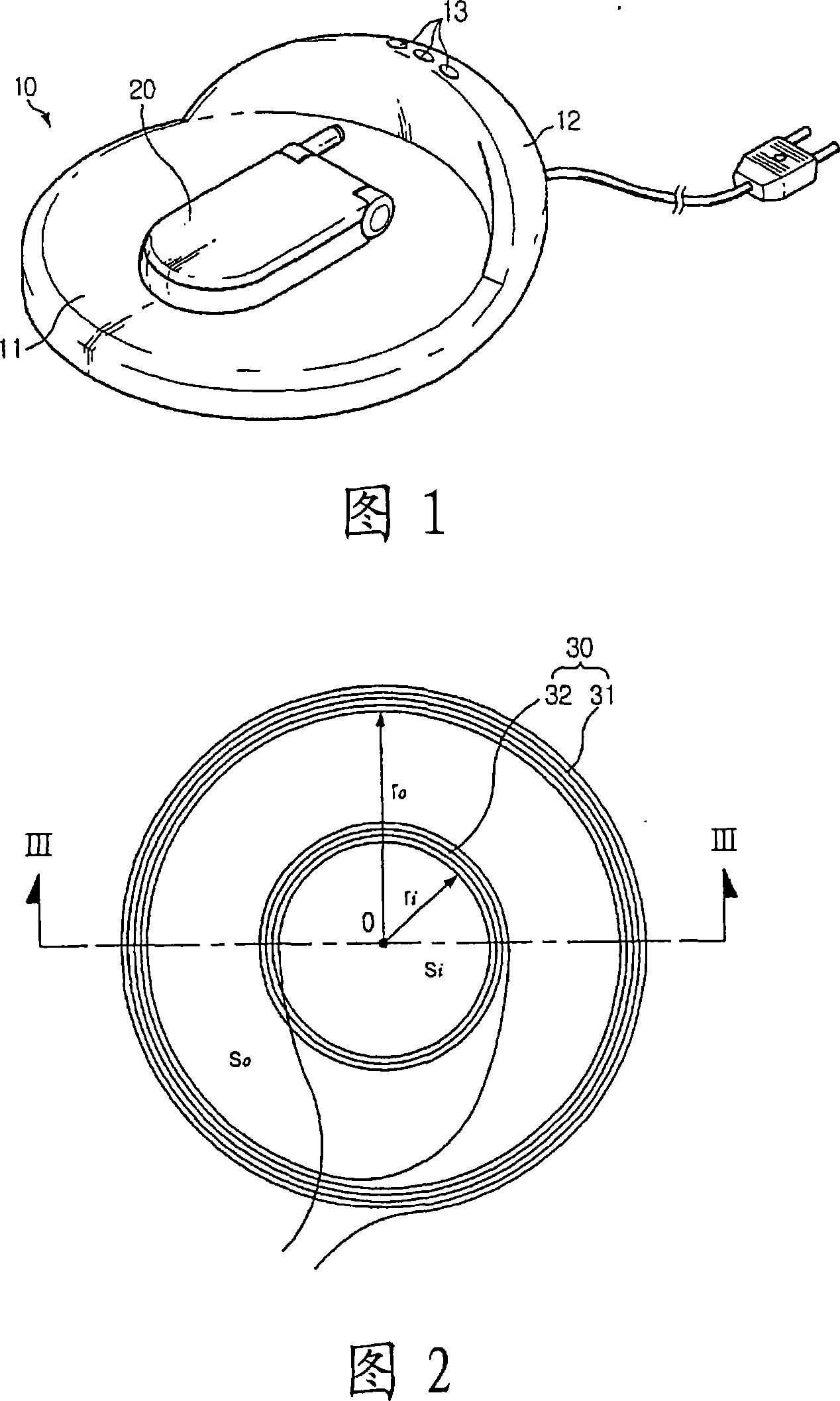
[0026] FIG. 1 is a perspective view illustrating charging of a storage battery of a portable e...


PUM


Abstract

The present invention provides a wireless charger with reduced variation in charging efficiency. The wireless charger charges the storage battery of the portable electronic device in a wireless manner, that is, in a non-contact or non-contact manner, so that no matter where the storage battery is located in the wireless charger, there is no serious change in charging efficiency. The wireless charger has a primary coil for generating a magnetic field to charge an object with the secondary coil through inductive coupling with the secondary coil. The primary coil includes: an outer coil arranged with a predetermined number of windings and a predetermined size; and at least one inner coil arranged to be included within the outer coil. The outer coil and the inner coil are arranged such that when a primary current is applied to the outer coil and the inner coil, magnetic fluxes generated in the outer coil and the inner coil are formed in the same direction.

Description

technical field [0001] The present invention relates to a wireless charger (for example, a wireless charger using a non-contact or non-contact method), and more particularly to a wireless charger having a structure capable of reducing charging efficiency depending on the location of an object to be charged. changes in position. Background technique [0002] Generally, portable electronic devices (eg, cellular phones, notebook computers, PDAs, etc.) have a battery therein so that the user can use them on the move. However, such portable electronic devices separately have a charger for charging the storage battery, and the charger is connected to a general power source to supply a charging current to the storage battery of the portable electronic device, thereby charging the storage battery. Meanwhile, in order for the charger to provide charging current to the storage battery of the portable electronic device, the charging body of the charger should be electrically connected...

Claims


Application Information

Patent Timeline
Patent Type & Authority Applications(China)
IPC IPC(8): H02J7/00
CPCH01F38/14H01F27/2871H02J50/10H02J50/402H02J7/0042H02J50/90H02J50/005H02J50/12H02J50/70
Inventor 权光熙朴东荣崔星旭韩燮文盛煜
Owner LG CABLE LTD (KR)
Why Eureka
Try Eureka