
Pneumatic balancing mechanical arm

A pneumatic balance, robotic arm technology, applied in the directions of manipulators, joints, manufacturing tools, etc., can solve the problems of balance problems, unilateral force on mobile devices, hidden safety hazards, etc., to achieve the effect of easy operation and rapid assembly

Inactive Publication Date: 2008-08-06
胡青
View PDF0 Cites 39 Cited by
  • Summary
  • Abstract
  • Description
  • Claims
  • Application Information

AI Technical Summary

Problems solved by technology

However, the current transfer devices are not flexible enough to move, and most of them can only be fixed in one position. A few movable transfer devices have not been properly handled due to the balance problem, which will cause unilateral force on the mobile device and cause potential safety hazards.
The mechanical arm of the transfer device generally cannot move freely, some can move horizontally, and some can move up and down, but they cannot move both horizontally and up and down
Moreover, during the movement of the mechanical arm of the transfer device, the horizontal state of the transported items cannot be guaranteed, causing deviations in the assembly position, making it difficult to install, and the quality of the product cannot be guaranteed.
At the same time, due to the unreasonable design of the mechanical arm of the transfer device, although the use of the mechanical arm to transport items saves time and effort compared with manual handling, the operator of the mechanical arm of the transfer device does not feel that the operation is very light and can do whatever he wants

Method used


Image

  • Pneumatic balancing mechanical arm
  • Pneumatic balancing mechanical arm
  • Pneumatic balancing mechanical arm

Examples


Embodiment Construction

[0019] Below in conjunction with accompanying drawing and embodiment the present invention is described in further detail:

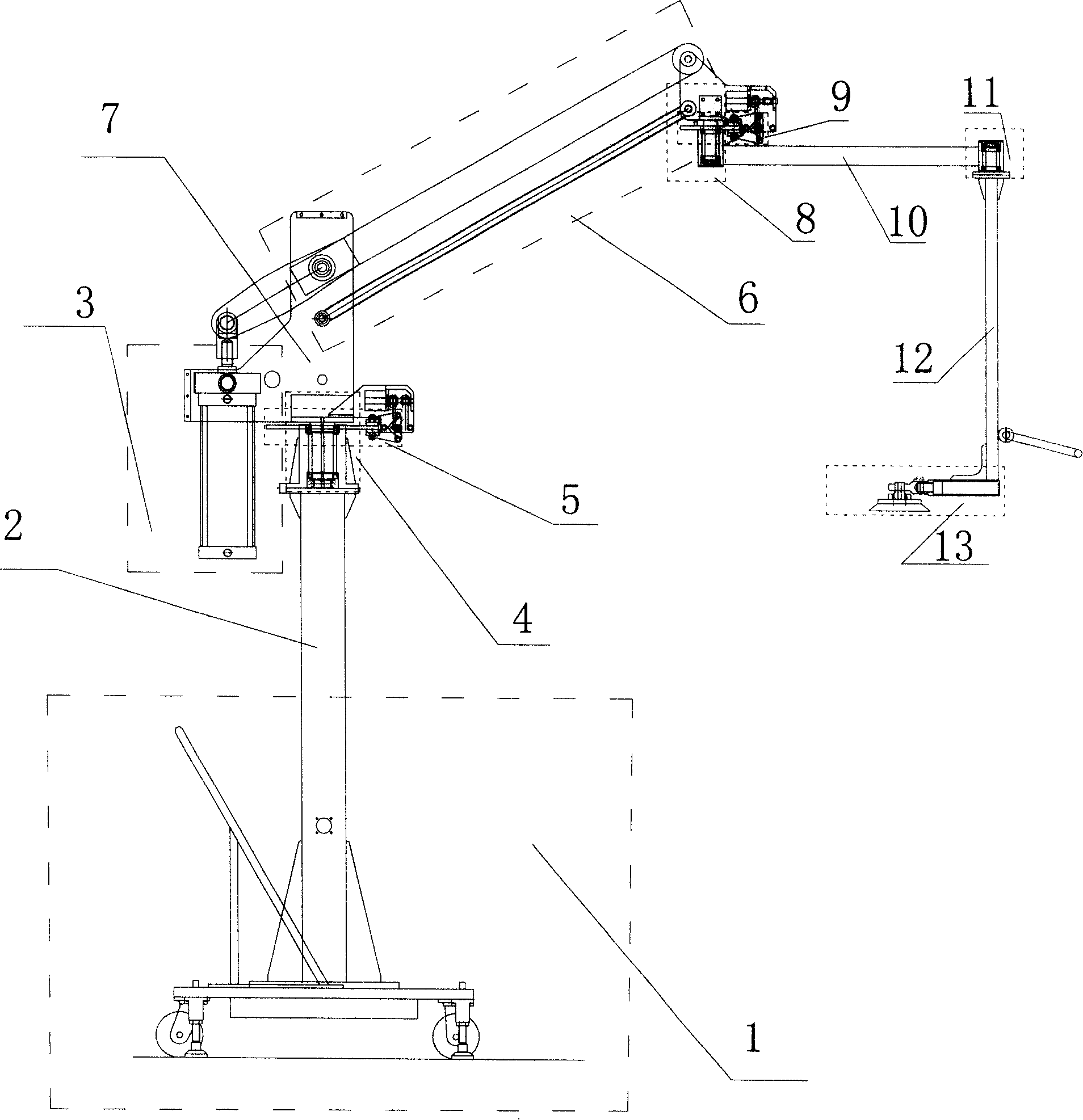
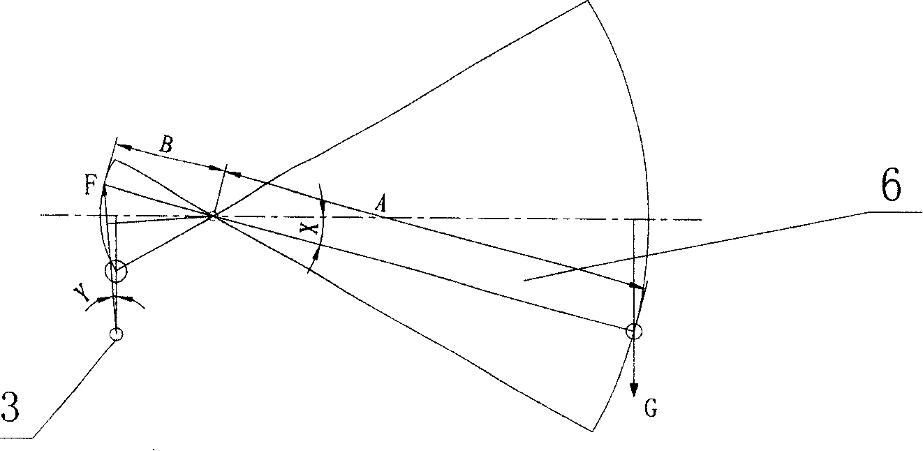
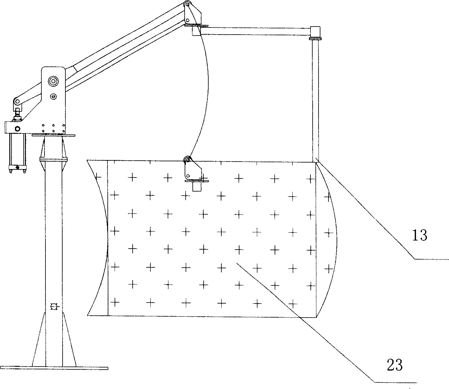
[0020] see figure 1 , a pneumatically balanced mechanical arm, which includes a pillar 2, a rotating body 7, an operating arm 12 and a clamp 13, and it also includes a base 1, a master cylinder 3, a rotary joint 4, a parallelogram mechanism 6, a rotary arm 10 and Dead point braking mechanism 5, wherein, the above-mentioned parallel four-bar linkage mechanism 6 is pivotally installed on the rotating body 7 through the middle part of a main long rod in the mechanism, and the above-mentioned parallel four-bar linkage mechanism 6 is fixed to the above-mentioned rotating body The main long rod on the body 7 is parallel to another secondary long rod that is pivotally installed on the rotating body 7 under the installation position of the main long rod, and the above-mentioned main cylinder 3 is located at one end of the long rod in the above-mentioned parallel...


PUM


Abstract

The invention provides an air balanced manipulator and an air control system of the manipulator, which comprises a base, a pillar, a rotator, an operating arm and a fixture. The manipulator also comprises a main cylinder, a brake cylinder, a rotary joint, parallel four connecting rods of organizations, a rotary arm, a dead point braking mechanism and a pneumatic control system. The air control system comprises a gas source, an airway, a vacuum switch and a vacuum generator. The manipulator can balance the carried articles at any position of the movable and solid space and meet the demand of accurate and rapid assembly, with a portable and free operation. The air control system can control the movement of the manipulator by controlling the movement of the main cylinder and the brake cylinder, ensure that the manipulator does not drop to pose a risk when the gas source stops supplying gas for accidents and avoid that the carried articles drop for misoperation, thereby ensuring the safety of operators and products in maximum.

Description

technical field [0001] The invention relates to a transfer device, in particular to a pneumatic balance mechanical arm. Background technique [0002] The transfer device is a device used to carry or move items. Directly use the transfer device to move items instead of manual movement in the production process, which can greatly save human resources. Using the device to transfer articles in the process of conveying articles can reduce the physical labor of the operator, ensure the quality of the product, and improve the rationality of the operation. However, the current transfer devices are not flexible enough to move, and most of them can only be fixed at one position. The balance of the few movable transfer devices is not properly handled, which will cause unilateral force on the mobile device and cause safety hazards. The mechanical arm of the transfer device generally cannot move freely, some can move horizontally, and some can move up and down, but they cannot move both...

Claims


Application Information

Patent Timeline
Patent Type & Authority Applications(China)
IPC IPC(8): B25J3/00B25J13/00B25J17/00B25J19/00
Inventor 胡青
Owner 胡青
Learn More