Eureka AIR delivers breakthrough ideas for toughest innovation challenges, trusted by R&D personnel around the world.

Gas turbine combusting device possessing upstream injection device

A technology of injection device and gas turbine, applied in combustion chamber, combustion method, combustion equipment, etc., can solve the problem of high cost of SCR method

Inactive Publication Date: 2008-08-06
GENERAL ELECTRIC CO
View PDF0 Cites 2 Cited by
  • Summary
  • Abstract
  • Description
  • Claims
  • Application Information

AI Technical Summary

Problems solved by technology

Unfortunately, the cost of the SCR method is relatively high

Method used

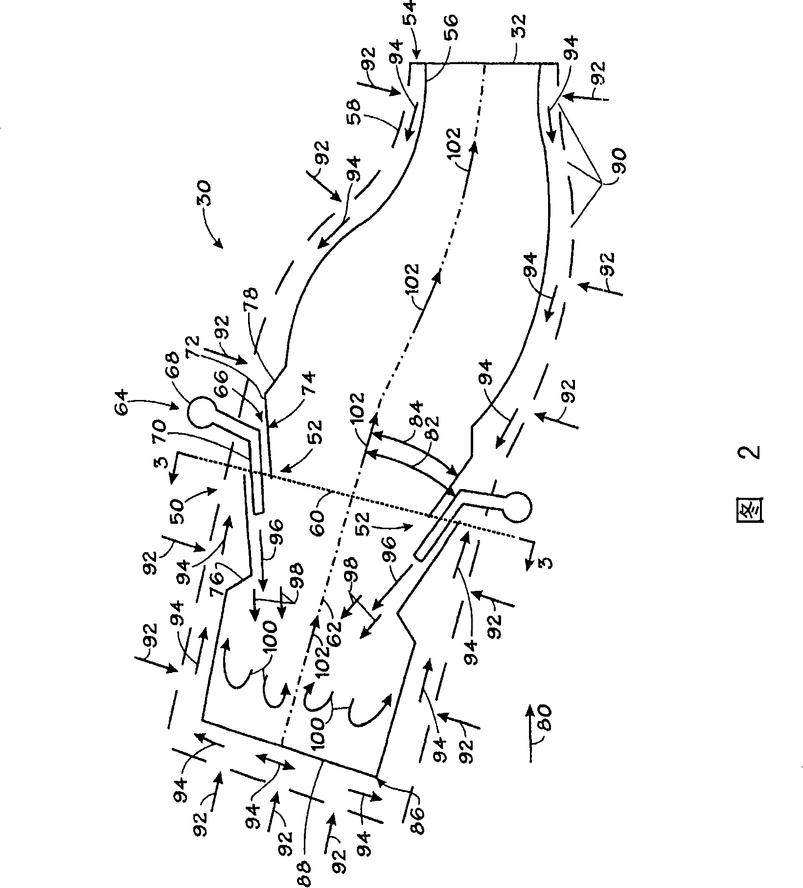
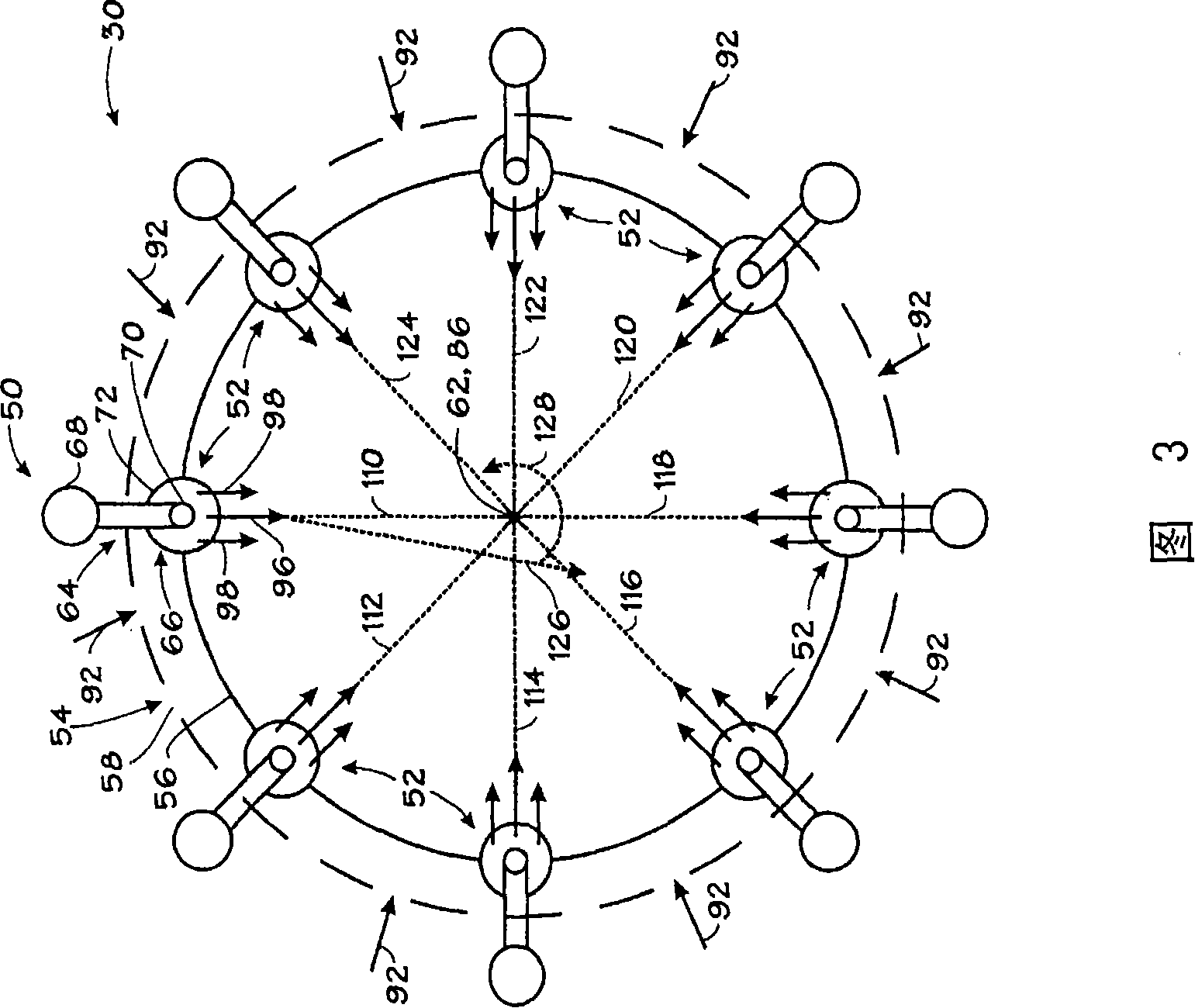

Image

  • Gas turbine combusting device possessing upstream injection device
  • Gas turbine combusting device possessing upstream injection device
  • Gas turbine combusting device possessing upstream injection device

Examples


Embodiment Construction

[0025] One or more specific embodiments of the invention are described below. In an effort to provide a concise description of these embodiments, not all features of an actual implementation are described in the specification. It should be appreciated that in the development of any such actual implementation, as in any engineering or design project, many implementation-specific decisions must be made to fulfill the developer's specific purposes, such as adapting to the constraints of the relevant system and the relevant business, Of course the purpose of one implementation may be different from another. Furthermore, it should be appreciated that such development planning might be complex and time consuming, but would nevertheless be a routine undertaking of design, fabrication, and production for those of ordinary skill having the benefit of this disclosure.

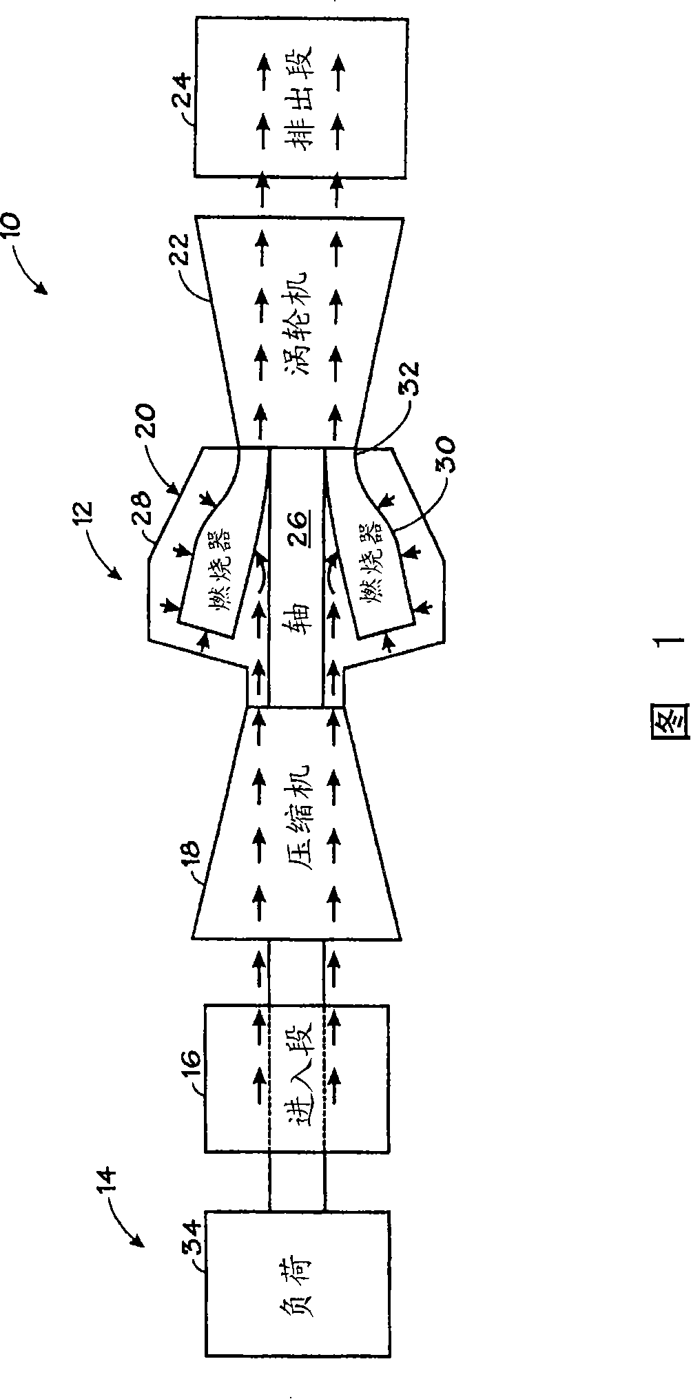
[0026] FIG. 1 is a block diagram of an exemplary system 10 including a gas turbine 12 for an application 14 in accord...


PUM


Abstract

A system comprises a counter-current injection device according to some embodiments. The counter-current injection device comprises fuel-air injection devices (50, 150) which are provided with fuel and air passages open to fuel and air injection orifices (70, 72, 156, 157, 210, 211), wherein the fuel and air injection orifices (70, 72, 156, 157, 210, 211) are arranged at the position deviated from center and opposite to an approximately longitudinal flow axis of an gas-turbine burner (30) in the approximate counter-current direction.

Description

Background technique [0001] It is hoped in this section to introduce the reader to various aspects of art that may be related to aspects of the present invention that are described and / or claimed below. It is believed that this discussion helps to provide the reader with background information to better understand the various aspects of the present invention. Accordingly, these statements should be read with the understanding that they are written in light of this point, and not as admissions of prior art. [0002] Combustion machines, such as gas turbines, produce various polluting emissions. For example, polluting emissions typically include carbon oxides (COx), nitrogen oxides (NOx), sulfur oxides (SOx), and particulate matter (PM). These polluting emissions are strictly regulated in the United States and elsewhere. NOx from gas turbines can be reduced by premixing fuel and air. Unfortunately, premixing produces an unstable flame that is difficult to stop, and the best ...

Claims


Application Information

Patent Timeline
IPC IPC(8): F23R3/00
Inventor J・M・海恩斯
Owner GENERAL ELECTRIC CO
Why Eureka
Eureka Blog
Learn More