LED supporter processing method for LED nude core test

A technology of LED bracket and processing method, applied in the direction of semiconductor/solid state device testing/measurement, electrical components, circuits, etc., can solve problems such as not reflecting the true level of LED bare cores, affecting comprehensive test results, and unfavorable LED bare core research.

Active Publication Date: 2008-08-06
JIANGXI LATTICEBRIGHT
View PDF2 Cites 13 Cited by
  • Summary
  • Abstract
  • Description
  • Claims
  • Application Information

AI Technical Summary

Problems solved by technology

Such a test method after packaging the LED chip cannot reflect the real level of the LED bare core, which is not conducive to the research on the LED bare core
For example, in order to test the fatigue test of LED

Method used


Image

  • LED supporter processing method for LED nude core test
  • LED supporter processing method for LED nude core test

Examples


Embodiment Construction

[0011] The invention provides a LED bracket processing method for LED bare core testing.

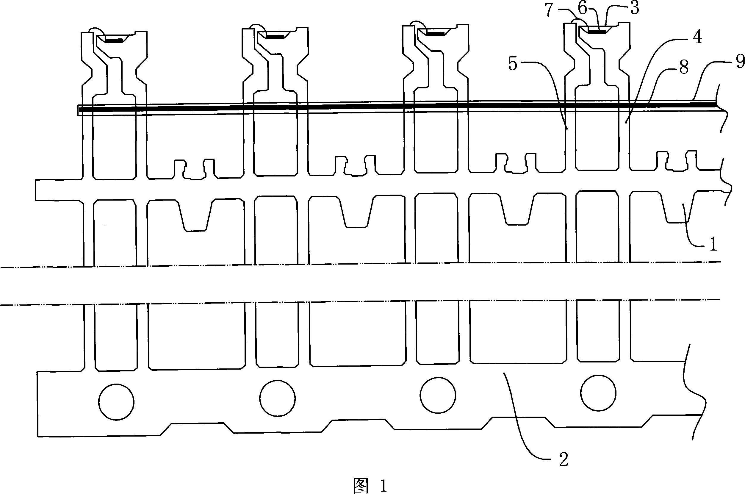
[0012] The structure of the product embodiment involved in the present invention is as follows, as shown in FIG. 1 . Generally, an LED bracket is provided with 20 bracket units (4 are shown in the figure, and the others are omitted) connected together, and the bracket units are connected together by the upper rib 1 of the bracket and the lower rib 2 of the bracket.

[0013] A single support unit is mainly composed of a bowl cup 3 , a first electrode pin 4 and a second electrode pin 5 for supporting the bowl cup 3 . An LED chip (i.e. bare core) 6 is placed in the bowl cup 3, and the LED chip 6 is sealed in the bowl cup 3 by epoxy resin. The wire 7 connects the second electrode pin 5 and the LED chip 6 . The upper rib 1 of the bracket connects multiple bracket units, and connects the first electrode pin 4 and the second electrode pin 5 .

[0014] A core wire 8 is wound between the first...


PUM


Abstract

The invention relates to an LED manufacturing technology which discloses a method for processing an LED rack for an LED bare core test and comprises a die attach and die bonding technology, a reeling and forming technology following the die attach and die bonding technology and a trimming technology; the reeling and forming technology comprises the following steps of: reeling a core wire between an upper rack tendon and a bowl cup, connecting a first electrode-pin with a second electrode-pin of each rack unit by the core wire and connecting the rack units in series, then applying epoxy resin on the core wire for curing and forming; and then carrying out the trimming technology. Compared with the prior art and with regards to the parameters of a LED chip, the LED manufacturing technology can be used to conduct a photoelectric test on an LED light with a bare core; therefore, the related parameters of the LED chip obtained are more accurate, which facilitates the research on LED chips.

Description

technical field [0001] The invention relates to a manufacturing process of LEDs, in particular to a packaging and testing method in the manufacturing process of LEDs. Background technique [0002] The prior art such as Chinese Patent No. is 200620018317, the patent titled "the bowl and cup structure of the LED support". The LED bracket described in this technology includes the upper rib of the bracket, the lower rib of the bracket and two electrode pins of the bracket unit. A bowl for placing LED chips is provided on one electrode pin, and the ribs on the support are connected to the two electrode pins. [0003] Similar to the prior art of the above-mentioned LED bracket, the test of the LED lamp is to first encapsulate the bare core of the LED with epoxy resin to form a finished product, and then test the finished product. The test can be carried out as described in Chinese Patent No. 200310115661, entitled "Method and System for Improving Testability of Packaged Integrat...

Claims


Application Information

Patent Timeline
IPC IPC(8): H01L33/00H01L21/66
Inventor 刘卫华熊细春江余李雄健
Owner JIANGXI LATTICEBRIGHT
Why Eureka
Try Eureka