Electric connector

A technology of electrical connectors and connectors, applied in the direction of connections, circuits, parts of connection devices, etc., can solve problems such as poor connection, loose cables, high risk, etc., and achieve the effect of improving the retention force

Inactive Publication Date: 2008-08-06
DDK LTD +1
View PDF2 Cites 7 Cited by
  • Summary
  • Abstract
  • Description
  • Claims
  • Application Information

AI Technical Summary

Problems solved by technology

In the shape of the fastening nut shown in the prior art of the above-mentioned Patent Document 1 and Patent Document 2, there is a danger that the above-mentioned cable will be caught on the fence surrounding the surroundings of industrial equipment or electronic and electrical equipment when being pulled. Higher, resulting in the above cable loosening, resulting in poor connection problems

Method used


Image

  • Electric connector
  • Electric connector
  • Electric connector

Examples


Embodiment Construction

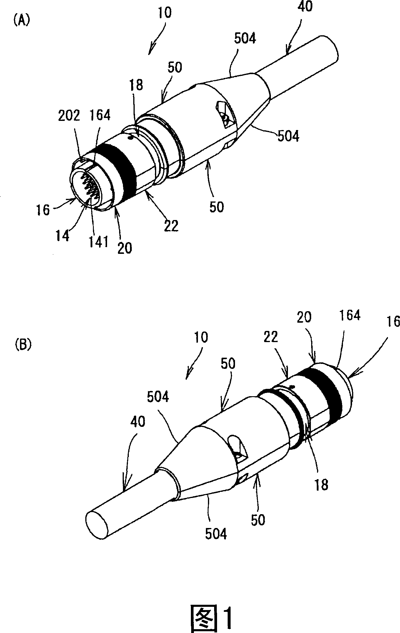
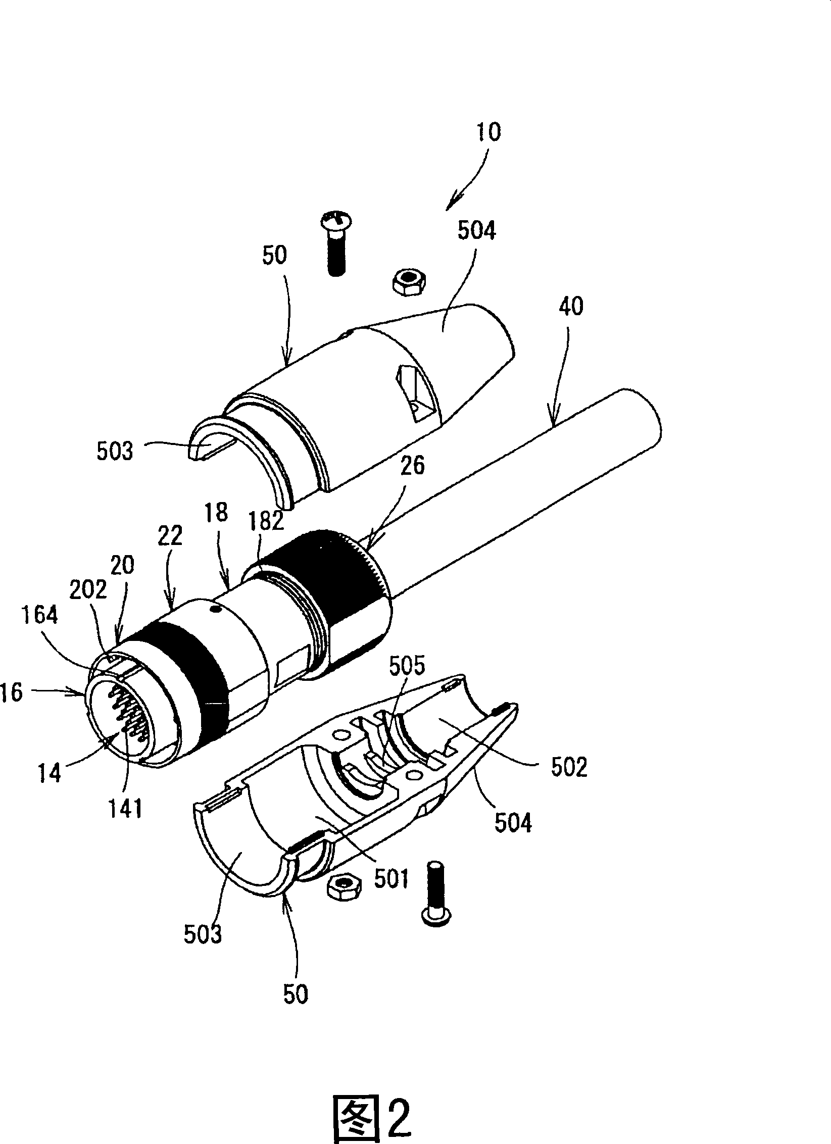
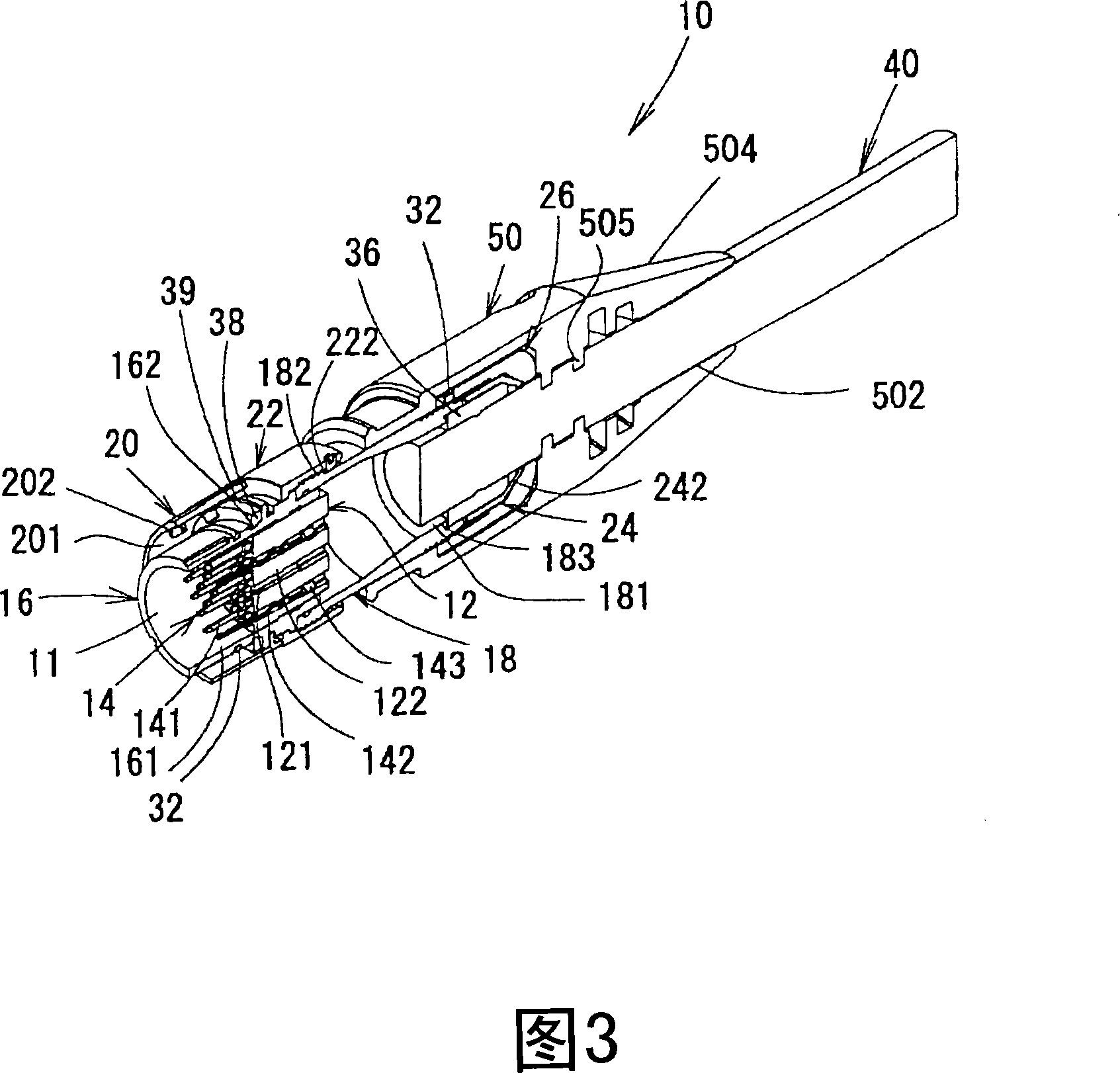
[0033] An embodiment of the electrical connector of the present invention will be described based on FIGS. 1 to 8 . FIG. 1(A) is a perspective view of the electrical connector of the present invention viewed from the direction of the fitting opening, and FIG. 1(B) is a perspective view of the electrical connector of the present invention viewed from the direction of the cable protruding. Fig. 2 is a perspective view of a state in which two cover members are disassembled. Fig. 3 is a cross-sectional view of the electrical connector of the present invention. FIG. 4(A) is a perspective view of a cable clamp, and FIG. 4(B) is a perspective view of a fastening nut. Fig. 5(A) is a perspective view of the electrical connector in a state where the cable clamp is removed and the rear housing is inserted into the cable, and Fig. 5(B) is a state in which the contacts are installed and the ground plate is inserted. stereogram of the object. Fig. 6 is a cross-sectional view of the elect...


PUM


Abstract

The invention provides an electric connecter (10) which is hard to hang on the enclosures surrounding the industrial devices and an electronic device when a cable (40) is drew and improves retentiveness of the cable (40) and does not cause poor connection. In the electric connecter having a plurality of contacts (14), insulators (12), plug casings (16), coupling rings (20), rear casings (18), couplings (22), cable clamps (24) and clamp nuts (26), the connecter has a mounting unit (501) having a cable clamp (24), a cable insertion unit (502) where the cable (40) enters and is connected to the mounting unit (501). By arranging a conic section (504) on a periphery of a projection of the cable, or by arranging at least one projection (505) on the cable insertion unit (502) or by arranging both of the conic section (504) and the projection (505), two cover components (50) are mounted on the cable projection side of the mounting mechanism, thus the purpose of the invention can be realized.

Description

technical field [0001] The present invention relates to an electrical connector with a cable used in industrial equipment, electronic and electrical equipment, etc., and relates to a structure that prevents snagging during use and enhances the holding force of the cable. Background technique [0002] A conventional electrical connector will be described. The above-mentioned electrical connector includes a plurality of contacts connected to at least a cable, an insulator that holds the contacts in a row, a plug housing that holds the insulator and has a holding mechanism for a coupling ring, and a coupling ring that has a mechanism for engaging with a counterpart connector. , a rear housing having an insertion portion into which the above-mentioned plug housing enters and having a mounting mechanism with a coupling ring and a fastening nut, a connector for fixing the rear housing to the above-mentioned plug housing, and a cable clamp for holding the above-mentioned cable , a...

Claims


Application Information

Patent Timeline
Patent Type & Authority Applications(China)
IPC IPC(8): H01R13/58H01R13/56
Inventor 江岛光治奥田祐司汤浅敬次郎
Owner DDK LTD
Why Eureka
Try Eureka