Foot rest for supporting tool machine

A technology of machine tools and feet, which is applied in the direction of manufacturing tools, workbenches, pivot connections, etc., can solve the problems of increasing storage space and easily tripping other objects, and achieves the effect of low cost and simple structure

Inactive Publication Date: 2008-08-13
REXON IND CORP LTD
View PDF1 Cites 6 Cited by
  • Summary
  • Abstract
  • Description
  • Claims
  • Application Information

AI Technical Summary

Problems solved by technology

After the support frame 10 is folded, the bottom ends of the two legs 14 will protrude from the side of the support platform 12, which will increase the required storage space and easily trip over other objects

Method used


Image

  • Foot rest for supporting tool machine
  • Foot rest for supporting tool machine
  • Foot rest for supporting tool machine

Examples


Embodiment Construction

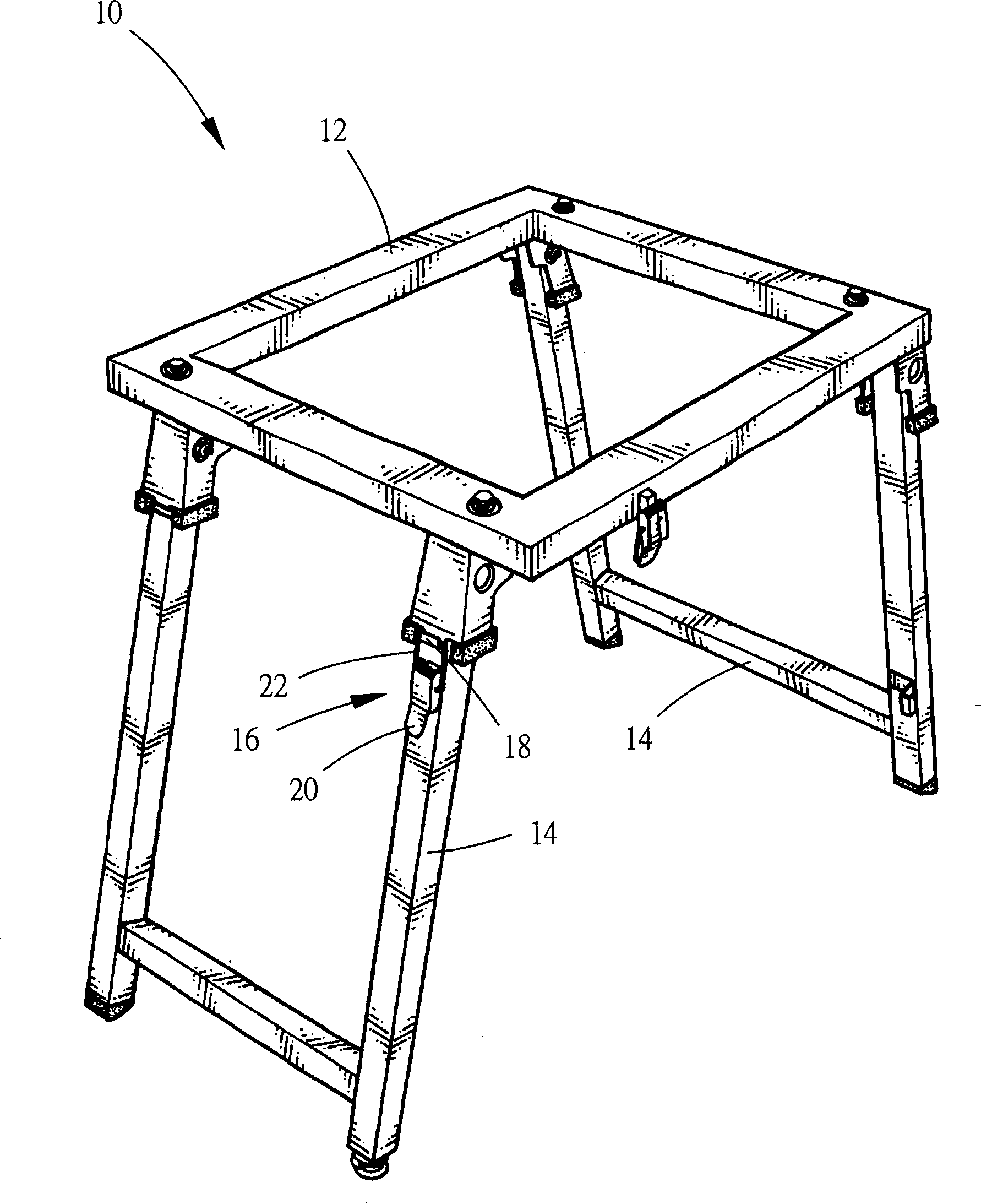
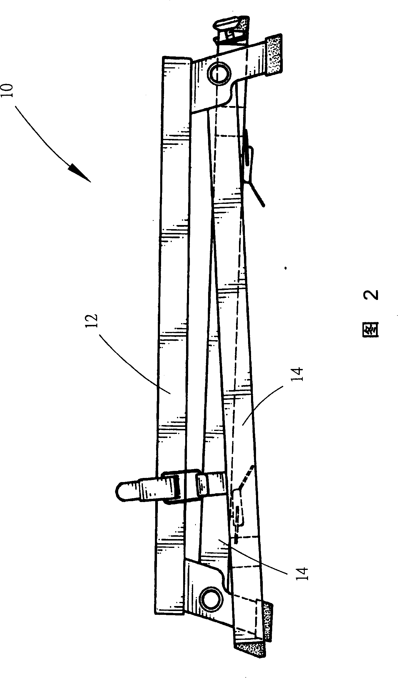
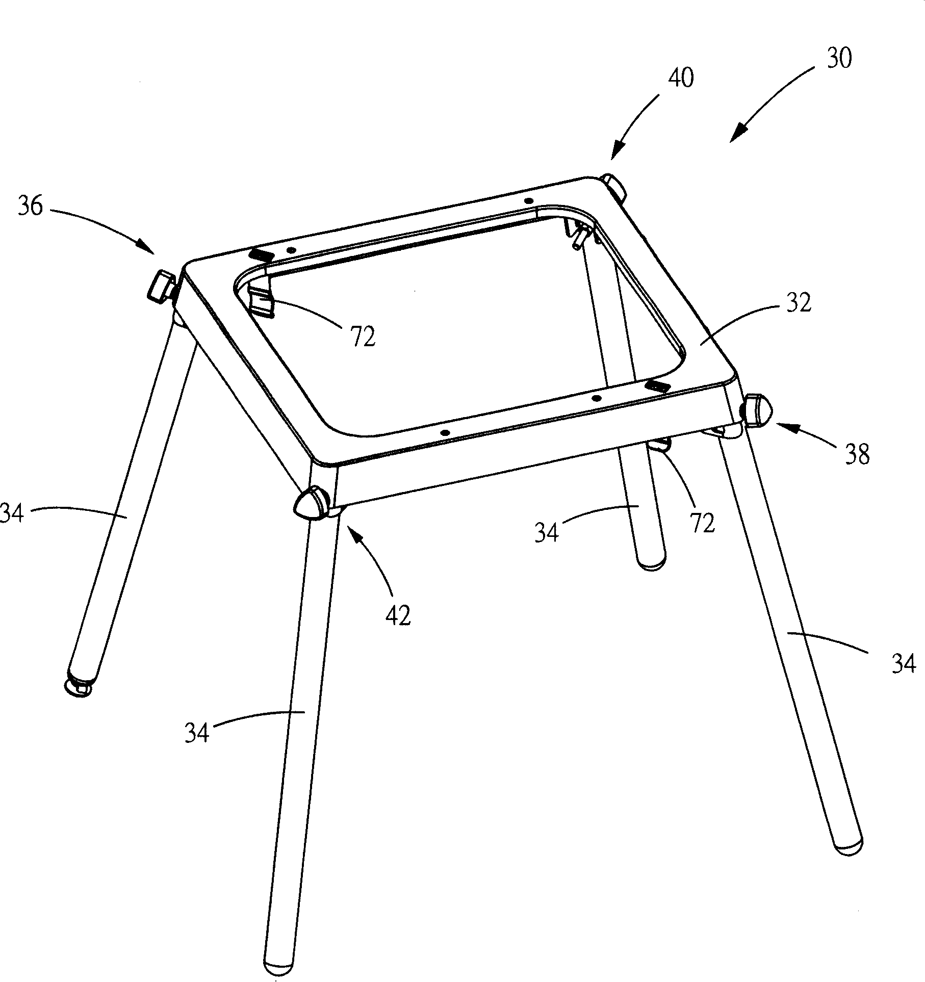
[0016] see image 3 and Figure 4 , image 3 It is a top perspective view of the tripod 30 in an unfolded state according to an embodiment of the present invention. The present invention is a tripod 30 for supporting a machine tool, the machine tool can be a table saw machine, a miter saw machine, a wire saw machine, a band saw machine, a drilling machine, a sanding machine, a planer, a cutting machine Etc., the stand 30 includes a platform 32, four legs 34 and a connecting component. The platform 32 is used to carry the tool machine above it, and the platform 32 can be in various shapes, such as a circular flat plate, a rectangular flat plate, a rectangular frame... In this embodiment, the rectangular frame is used as the example for illustration. The four legs 34 are respectively arranged at the four corners of the platform 32 and are located below the platform 32 in the shape of a round rod. When in the unfolded state, the four legs 34 stand on the ground to prop up the...


PUM


Abstract

A tripod in the present invention comprises: a platform, four feet and a linking part. The platform is used for supporting the tools machine and the top of it, and four feet is used for supporting the platform in the unfolding condition. The linking part comprises the first linking equipment, the second linking equipment, the third linking equipment and the fourth linking equipment, all of which link with four feet separately and connect with the platform. A first linking line is set between the first linking equipment and the second linking equipment for connecting with each other and the third and fourth linking equipment lying in the side of the first line. The stabilizer linking with the first linking equipment is near to the first linking line and far away from the third linking equipment; the stabilizer linking with the second linking equipment is near to the first line and away from the fourth linking equipment.

Description

【Technical field】 [0001] The present invention relates to a tripod, in particular to a collapsible tripod for supporting a machine tool. 【Background technique】 [0002] see figure 1 , figure 1 It is a perspective view of a conventional support frame 10 in a deployed state. U.S. Patent No. 6,607,015 discloses a collapsible support frame 10 for supporting a circular saw machine, which has a support platform 12, two H-shaped legs 14 pivotally mounted on the support platform 12, and a plurality of fixing members 16, each of which A fixing member 16 has a buckle groove 18 formed on the bottom of the supporting platform 12 and protruding outward, a plate 20 pivotally mounted on the leg 14 , and a U-shaped ring 22 pivotally mounted on the plate 20 . [0003] In this way, when the support frame 10 is to be folded, only the U-shaped rings 22 are separated from the buckle grooves 18, and then the two H-shaped legs 14 are pivoted inward; At 10 o'clock, you only need to pivot the tw...

Claims


Application Information

Patent Timeline
Patent Type & Authority Applications(China)
IPC IPC(8): B25H1/04B25H1/06F16C11/04
Inventor 陈荣火
Owner REXON IND CORP LTD
Why Eureka
Try Eureka