
Injection mold assembly

A technology of injection molding and metal molds, applied in the field of metal molds, can solve the problems of reduced heating and cooling efficiency, poor demoulding, and reduced forming accuracy

Inactive Publication Date: 2008-08-13
NIPPON PLATEC CO LTD
View PDF1 Cites 4 Cited by
  • Summary
  • Abstract
  • Description
  • Claims
  • Application Information

AI Technical Summary

Problems solved by technology

As a result, the efficiency of heating and cooling is reduced. In addition, a temperature difference occurs between the fixed mold part and the movable mold part, and there is a possibility that a temperature difference occurs in the cavity, which becomes a cause of a reduction in molding accuracy. In addition, Problems such as poor mold release occur

Method used


Image

  • Injection mold assembly
  • Injection mold assembly
  • Injection mold assembly

Examples


Embodiment Construction

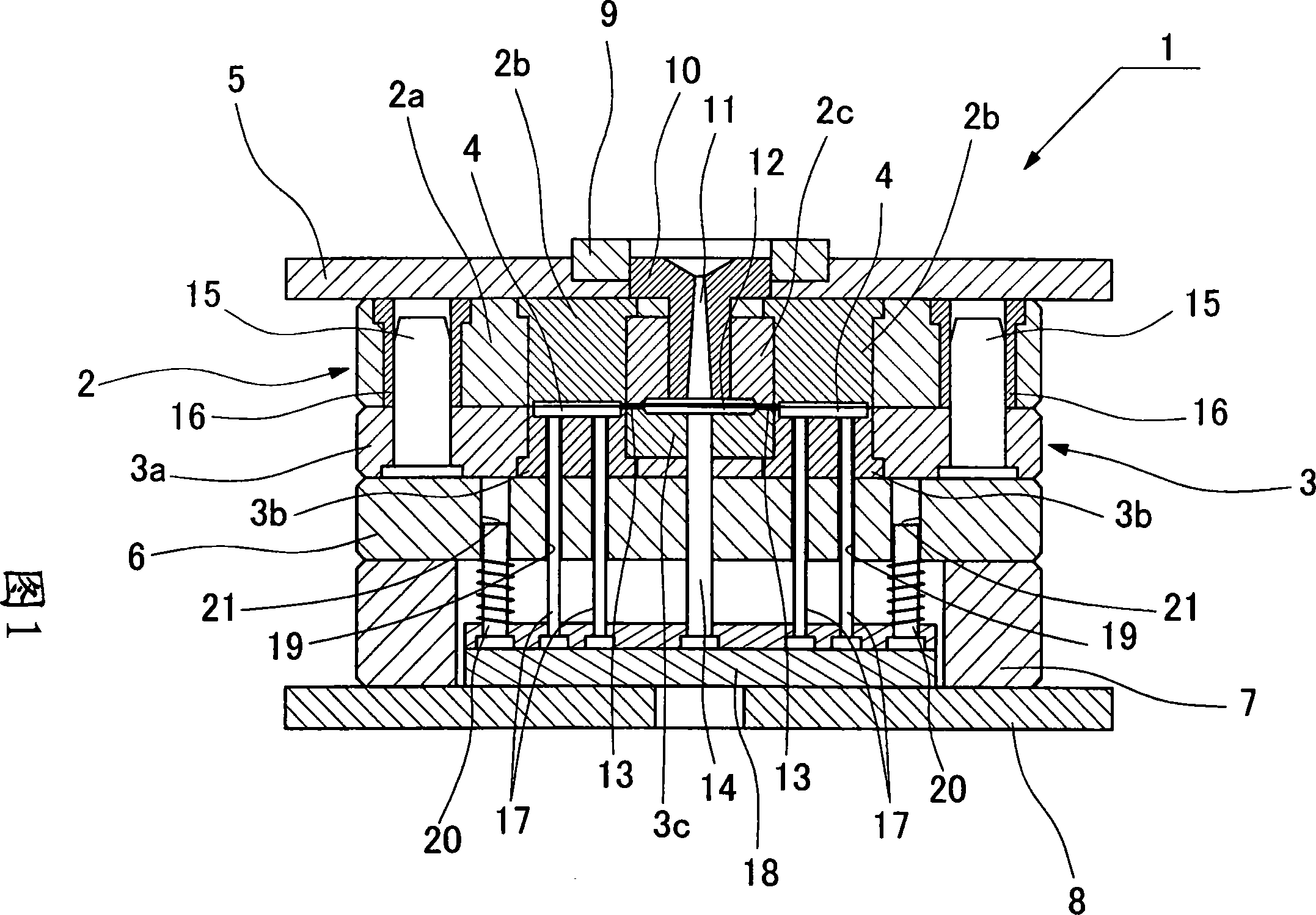
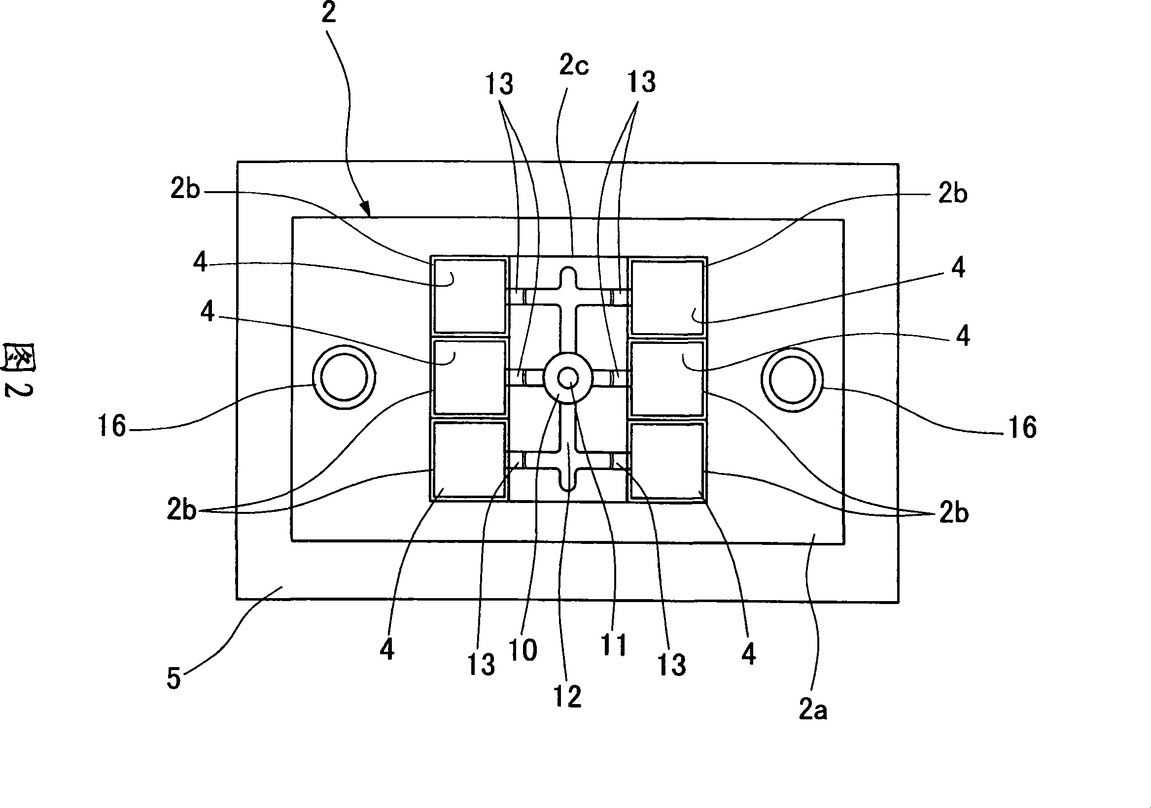
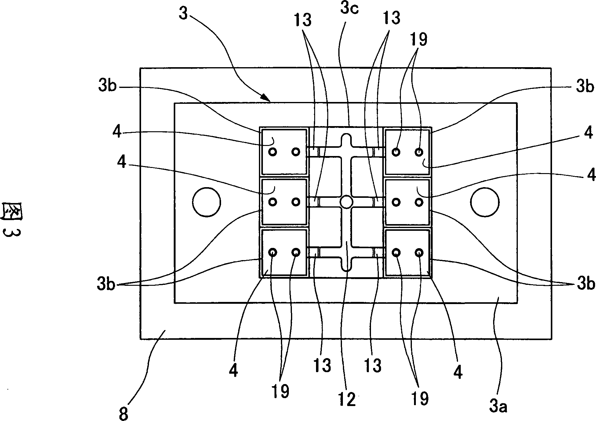
[0024] Embodiments of the present invention will be described below with reference to the drawings. Fig. 1 is a longitudinal sectional view showing a metal mold for injection molding. As can be seen from this figure, the molding die 1 has a fixed mold member 2 shown in FIG. 2 and a movable mold member 3 shown in FIG. , forming a cavity 4 therebetween. Here, both the fixed mold member 2 and the movable mold member 3 are formed by attaching cores 2b, 3b to die plates 2a, 3a, and a cavity 4 is formed between the cores 2b, 3b. In addition, although the fixed mold member 2 and the movable mold member 3 are constituted by members respectively different from the core and the die plate, they may be constituted by an integral member.

[0025] The fixed mold part 2 is fixed on the fixed-side mounting plate 5 , and the movable mold part 3 is connected to the movable-side mounting plate 8 via the support plate 6 and the spacer 7 . A positioning ring 9 is installed on the fixed-side mou...


PUM

PropertyMeasurementUnit
thermal conductivityaaaaaaaaaa

Abstract

The invention discloses an injection mold metal member, in this invention, a cavity is formed between stationary and movable mold members, and a runner is connected to a gate to the mold cavity to supply a molten resin material thereto. The stationary and movable mold members have bodies of an aluminum alloy of high heat conductivity and light weight. Iron base plating is applied at least to transfer wall surfaces of the cavity, leaving and exposing other wall surfaces in a non-plated state.

Description

technical field [0001] The present invention relates to a metal mold for injection molding, and more particularly, to a metal mold for injection molding composed of a mold using an aluminum alloy as a base material. Background technique [0002] Metal molds for injection molding generally use metal molds made of steel. Although the metal molds made of steel have the advantages of durability and the ability to maintain replication accuracy even after repeated molding, there are difficulties in the manufacture of metal molds. In addition, The production time is long, and further, there is a problem that the production cost increases due to these factors. Also, there are many deficiencies in thermal conductivity and weight. In consideration of the above points, various materials other than steel have been put into practical use as the material of the mold. Among them, the metal mold made of aluminum has good workability, and shortens the mold manufacturing time and reduces th...

Claims


Application Information

Patent Timeline
Patent Type & Authority Applications(China)
IPC IPC(8): B29C45/26B29C33/38
CPCB29C45/37B29K2905/02B29C33/56B29C33/38B29K2705/12B29C45/26
Inventor 及川涉浪冈健
Owner NIPPON PLATEC CO LTD
Features
  • Generate Ideas
  • Intellectual Property
  • Life Sciences
  • Materials
  • Tech Scout
  • Unparalleled Data Quality
  • Higher Quality Content
  • 60% Fewer Hallucinations
Learn More