Heat converter and air conditioner possessing the heat converter

A technology for heat exchangers and air conditioners, applied in air conditioning systems, evaporators/condensers, heating methods, etc. Uniformity and other issues, to achieve the effect of good heat exchange performance, uniform temperature distribution, and flexible layout

Inactive Publication Date: 2008-08-13
AIR INT THERMAL SYST R&D (SHANGHAI) CO LTD
View PDF0 Cites 8 Cited by
  • Summary
  • Abstract
  • Description
  • Claims
  • Application Information

AI Technical Summary

Problems solved by technology

[0007] Since the heat exchange medium fluid continuously exchanges heat with the surrounding air during the flow process, the temperature of the heat exchange medium fluid along the flow direction changes gradually (increases or decreases), resulting in uneven temperature distribution of the heat exchanger, thus heat exchange The heat transfer performance of the device is low
[0008] Moreover, considering the flow pattern of the heat exchange medium fluid in the second header

Method used


Image

  • Heat converter and air conditioner possessing the heat converter
  • Heat converter and air conditioner possessing the heat converter
  • Heat converter and air conditioner possessing the heat converter

Examples


Example Embodiment

[0052] In order to enable those skilled in the art to better understand the technical solutions of the present invention, the present invention will be further described in detail below with reference to the accompanying drawings and specific embodiments.

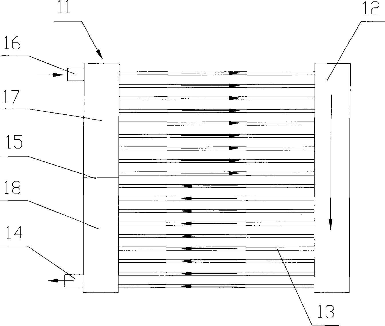
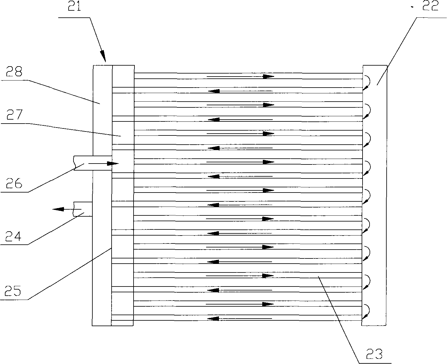
[0053] Please refer to figure 2 , figure 2 It is a schematic structural diagram of the first specific implementation of the heat exchanger of the present invention.

[0054] Such as figure 2 As shown, the arrow direction shown in the figure indicates the flow direction of the heat exchange medium fluid.

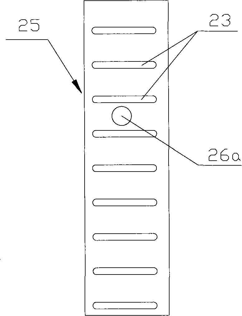
[0055] The heat exchanger provided in this embodiment specifically includes a first header 21 and a second header 22 that are arranged in parallel and are hollow, and a plurality of them are in communication with the first header 21 and the second header 22 and are parallel to each other. The manifold 23, the internal flow splitter 25 installed inside the first header 21, the inlet pipe 26 and the outlet pipe 24.

[0056] T...


PUM


Abstract

The invention discloses a heat-exchanger, comprising: a first collecting pipe and a second collecting pipe which are hollow and parallel arranged, a plurality of dividing pipes vertical to the first collecting pipe and the second collecting pipe, an internal flowing divider in the first collecting pipe, an inlet pipe and an outlet pipe. The internal flowing divider divides the first collecting pipe into an inlet collecting chamber and an outlet collecting chamber which are separated from each other, and the inlet pipe is communicated with the inlet collecting chamber, and the outlet pipe is communicated with the outlet collecting chamber. The dividing pipes are separated into two groups, wherein, one group is communicated with the inlet collecting chamber, another group is communicated with the outlet chamber, and the adjacent dividing pipes form individual U-shaped channels which are disposed in interval in order to achieve even temperature distribution for the heat-exchanger with excellent heat-exchange performance. The invention also discloses an air-conditioner with the heat-exchanger.

Description

technical field [0001] The present invention relates to a heat exchanger, and more particularly to an internal flow split heat exchanger. The present invention also relates to an air conditioner provided with the above-mentioned heat exchanger. Background technique [0002] At present, heat exchangers are mainly used in evaporators and condensers of heaters, refrigerators, and air conditioners, and are tools for heat exchange. Generally, the heat exchanger has two headers with a certain interval and parallel to each other, and shunt pipes parallel to each other and whose two ends communicate with the headers. There are cooling fins between the shunt pipes which are more conducive to heat exchange. The heat exchange medium fluid (liquid refrigerant or heat medium) circulates in the header and distribution pipe of the heat exchanger, and the heat exchange medium fluid flowing in the header and distribution pipe performs heat exchange with the air around the heat exchanger. T...

Claims


Application Information

Patent Timeline
IPC IPC(8): F25B39/00F24F1/00
Inventor 曾欣叶粮
Owner AIR INT THERMAL SYST R&D (SHANGHAI) CO LTD
Why Eureka
Try Eureka