
Method and device for supply to a magnetic coupler

A magnetic coupler, power supply current technology, applied in output power conversion devices, irreversible DC power input conversion to AC power output, electrical components and other directions, can solve problems such as bulkiness, and achieve the effect of reducing size

Inactive Publication Date: 2008-08-13
CENT NAT DE LA RECHERCHE SCI +2
View PDF0 Cites 7 Cited by
  • Summary
  • Abstract
  • Description
  • Claims
  • Application Information

AI Technical Summary

Problems solved by technology

[0008]The magnetic coupler thus provided works correctly, but is bulky

Method used


Image

  • Method and device for supply to a magnetic coupler
  • Method and device for supply to a magnetic coupler
  • Method and device for supply to a magnetic coupler

Examples


Embodiment Construction

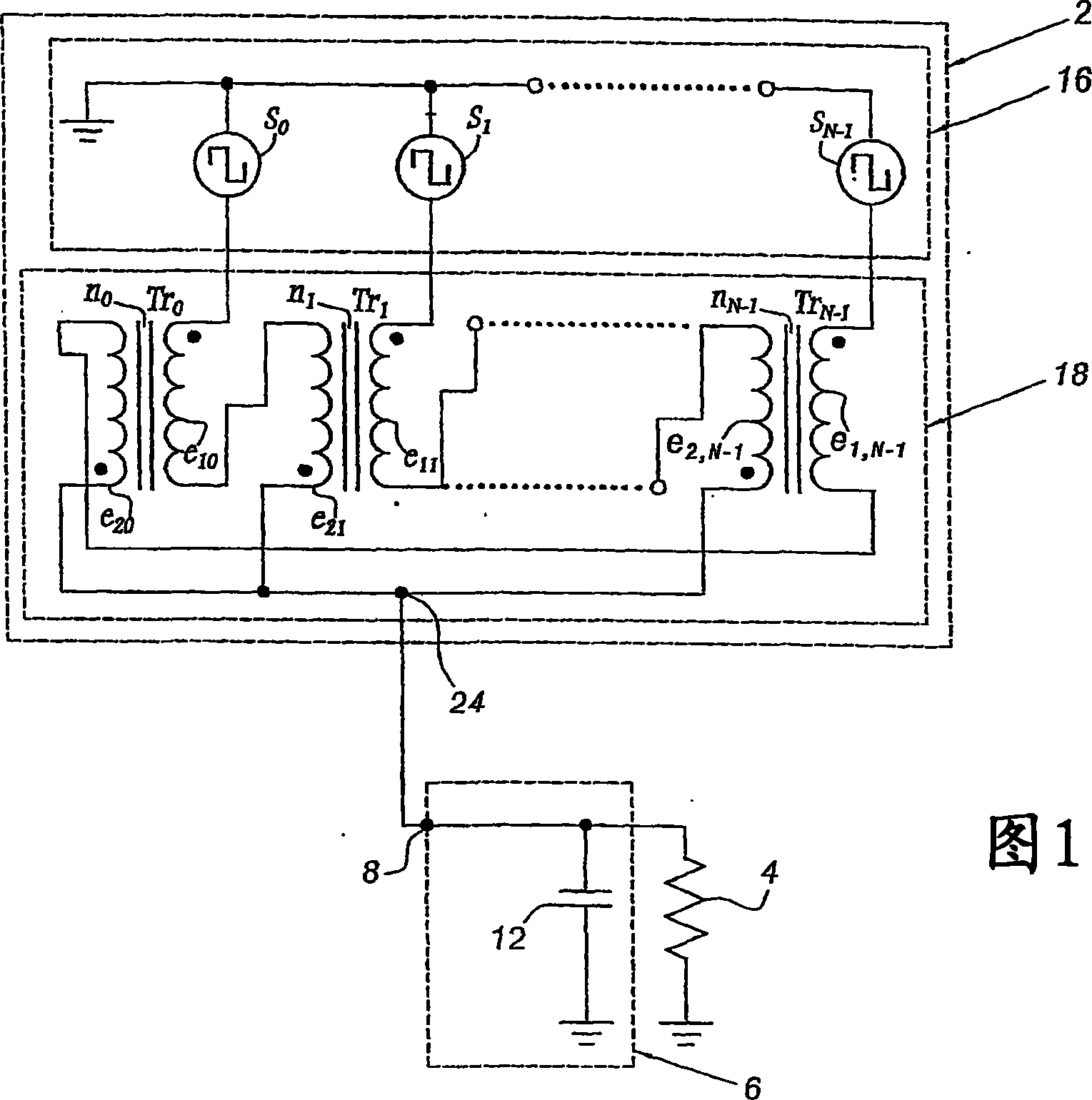
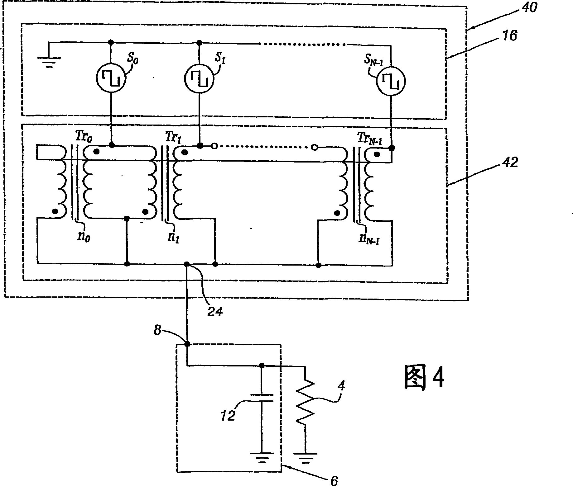
[0046] FIG. 1 shows a device 2 for powering an electric dipole 4 . In this case, the dipole 4 is connected to the device 2 by means of a filter 6 equipped with an input 8 .

[0047] Dipole 4 is, for example, a resistor.

[0048] Filter 6 is, for example, a filter including only filter capacitor 12 connected in parallel to each end of dipole 4 . In this case, device 2 makes it possible to avoid the use of filter inductors.

[0049] The device 2 comprises a polyphase voltage source 16 and a magnetic coupler 18 for connecting the voltage source 16 to the dipole 4 .

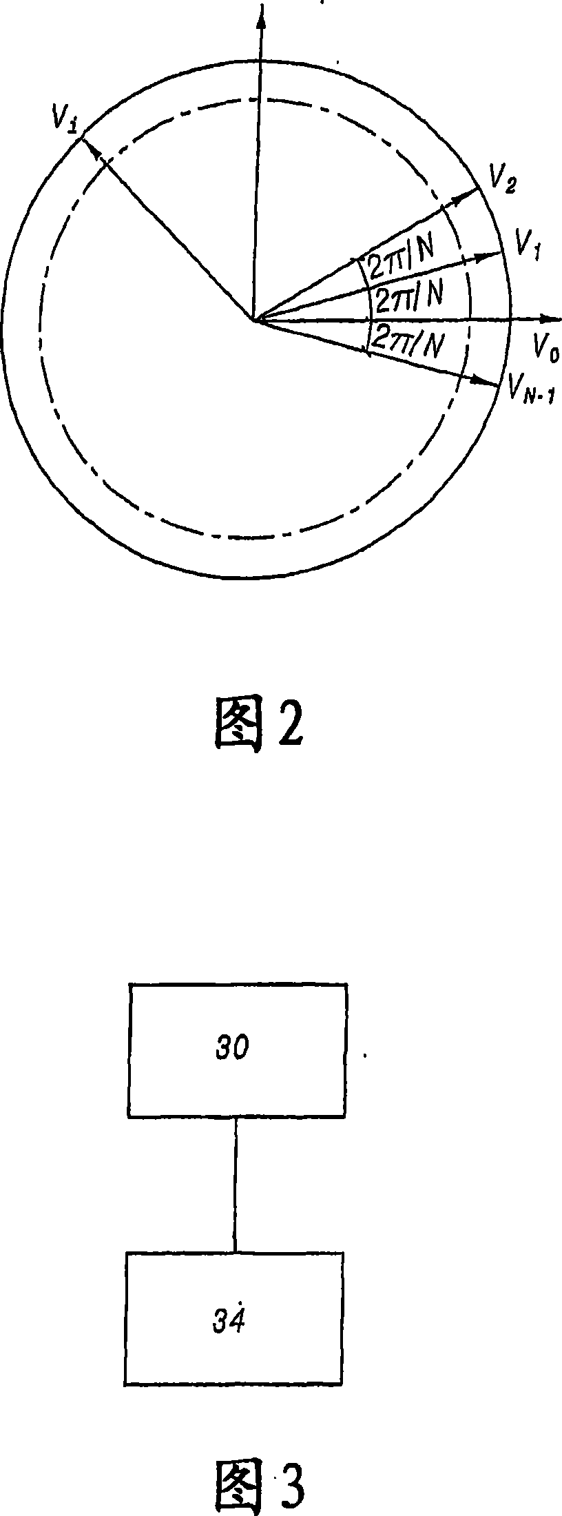
[0050] The power source 16 is an N-phase power source, where N is an integer greater than or equal to 4. The power supply 16 thus provides N voltages Vi, where the value i is the number of phases between 0 and N-1. By convention, the angular offset between voltages V0 and Vi is equal to 2πi / N. Thus at voltage V0 to V N-1 The angular offsets between are regularly distributed between 0 and 2π radians, as shown in...


PUM


Abstract

The invention relates to a method for supply to a magnetic coupler comprising several pairs of windings, each pair being formed from a first and a second adjacent paired winding, magnetically coupled to each other by means of a core of magnetic material. The method further consists of supplying the first winding of each pair with a supply voltage or current out of phase by an angle a with relation to the supply voltage or current for the second winding of the same pair. The absolute value of the angle a is greater than or equal to 4p / N for at least one pair of windings.

Description

technical field [0001] The present invention relates to a method and apparatus for providing a magnetic coupler. Background technique [0002] Magnetic couplers (polyphase-to-phase transformers) are used, for example, to connect loads to a multiphase power supply. [0003] It is known to use a multi-phase power supply that can generate N cycles of supply current or voltage angularly offset from each other, where N is an integer greater than or equal to 4. The angular offset between the applied supply currents or voltages is evenly distributed between 0 and 2π radians. An angular shift of 2π radians corresponds to a period of the current or voltage. [0004] Known magnetic couplers comprise several pairs of windings, each pair consisting of a first and a second adjacent winding, which are magnetically connected to each other by means of a core or core made of magnetic material. Different structures of known magnetic couplers are described in the following articles: [000...

Claims


Application Information

Patent Timeline
Patent Type & Authority Applications(China)
IPC IPC(8): H02M7/48
CPCH02M7/493H02M7/48
Inventor 泰瑞·安东尼·梅纳德弗兰柯伊斯·福莱斯特弗莱德里克·理查德尤埃里克·拉博莱
Owner CENT NAT DE LA RECHERCHE SCI
Learn More