Compact spinning apparatus of spinning frame

A spinning frame, compact technology, applied in the direction of spinning machines, textiles, papermaking, drafting equipment, etc., can solve the problems of "hairiness" and achieve the effects of reduced turn-up angle, less yarn breakage and easy twist

Inactive Publication Date: 2008-08-20
朱爱萍
View PDF2 Cites 6 Cited by
  • Summary
  • Abstract
  • Description
  • Claims
  • Application Information

AI Technical Summary

Problems solved by technology

[0004] The object of the present invention is to provide a spinning frame compact spinning device that effectively solves the "hairiness" problem in the spinning process of the spinning frame

Method used


Image

  • Compact spinning apparatus of spinning frame
  • Compact spinning apparatus of spinning frame
  • Compact spinning apparatus of spinning frame

Examples


Embodiment Construction

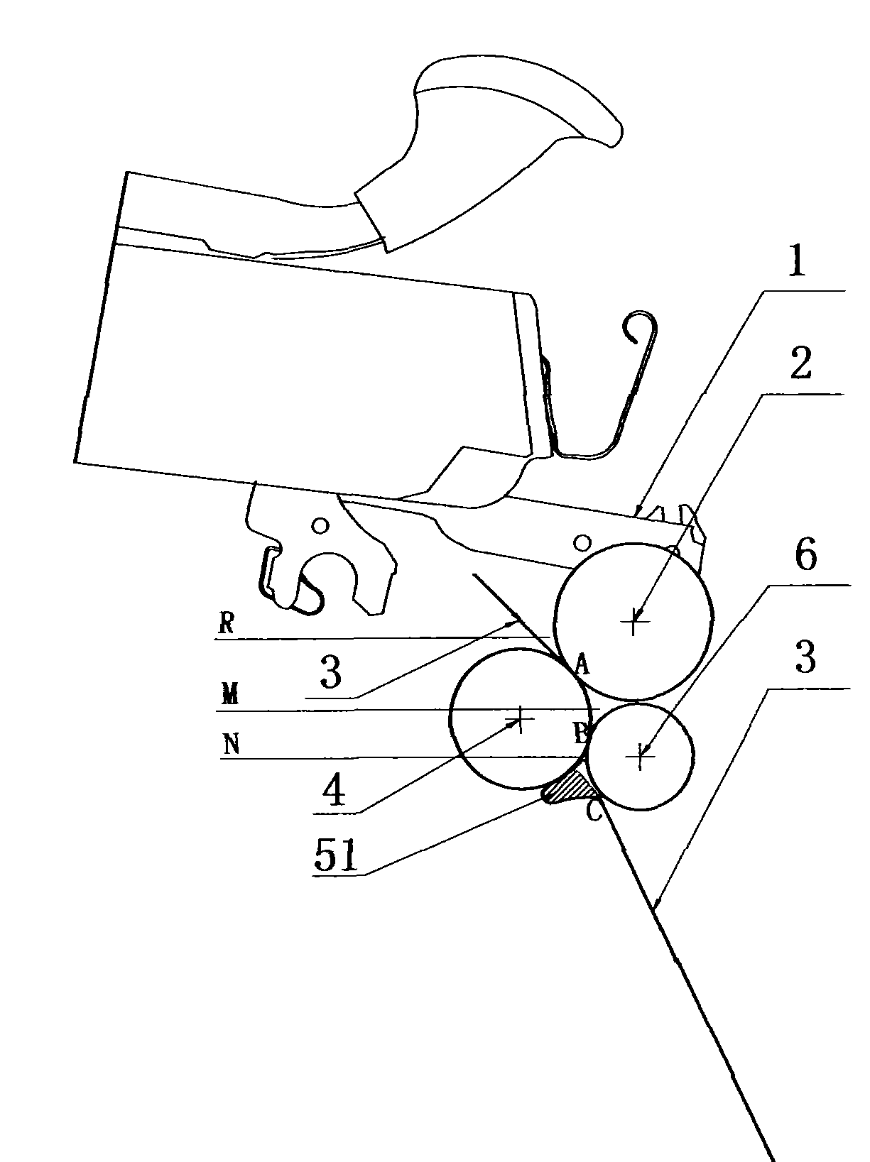
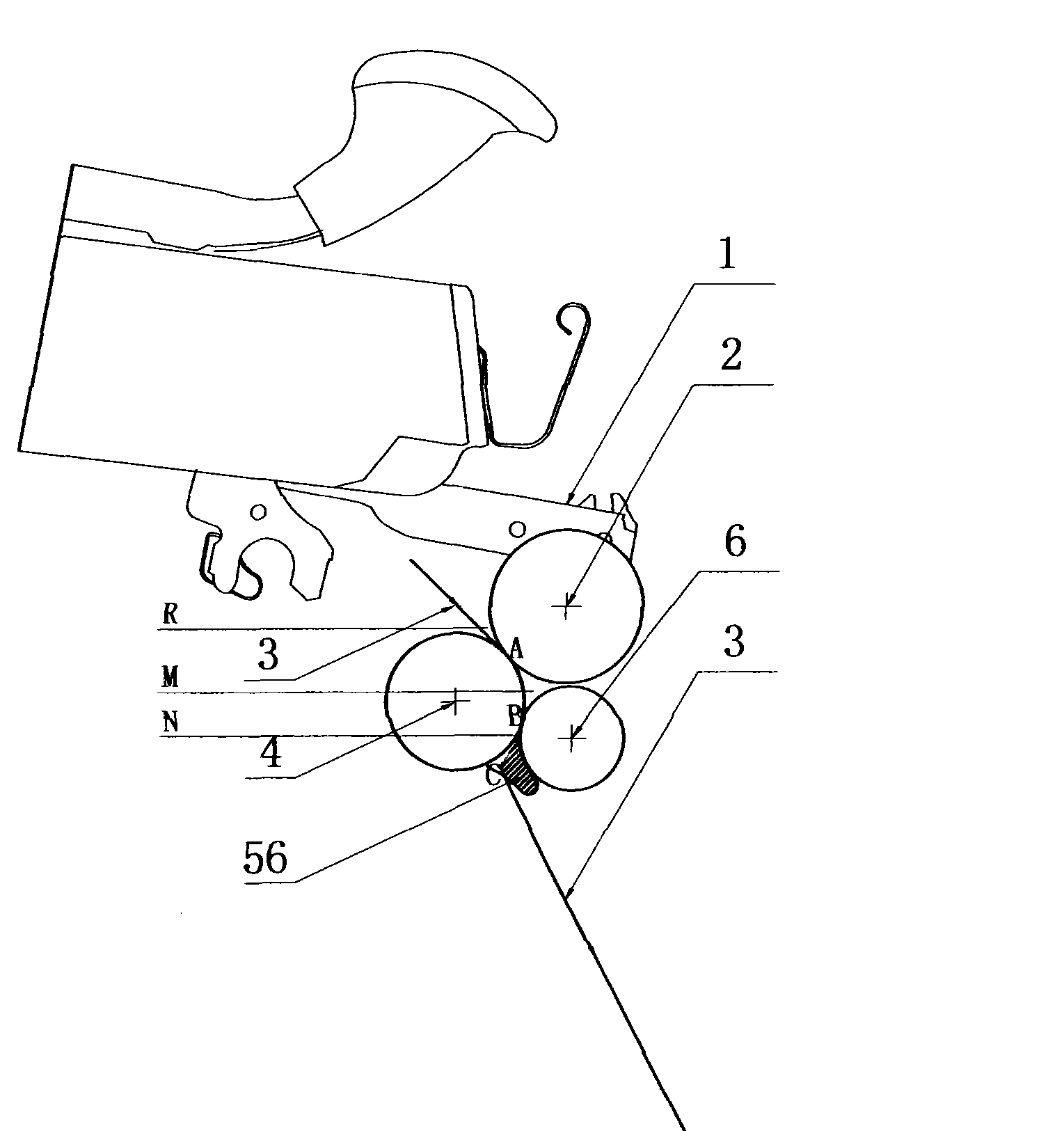
[0025] like figure 1 As shown, the bottom roller 2 is installed on the cradle 1 of the spinning frame, and the bottom roller 4 is installed under the cradle 1 and pressed tightly on the bottom roller 2. A pair of bottom roller 2 and bottom roller 4 are formed. The drafting pressure roller drafts the yarn 3, the output pressure roller 6 is pressed against the bottom roller 4, and the converging member 5 is installed in the converging area N.

[0026] The contact area A formed between the bottom roller 4 and the bottom top roller 2 constitutes a drafting area R between the pre-drafting device and the output end A of the draft pressure roller composed of the bottom roller 4 and the bottom top roller 2; The contact area B formed by the bottom roller 4 and the output pressure roller 6, the yarn guide area M is formed between the output end A of the drafting zone R and the output end B of the bottom roller 4 and the output pressure roller 6, extending from the output end B A bundle...


PUM


Abstract

The invention discloses a tight spinning device of a spinning machine, which belongs to the technical field of spinning mechanical technology and includes a lower leather roller mounted on a cocket centring of the spinning machine. A lower roller is mounted below the cocket centring and tightly pressed on the lower leather roller. An output compression roller is tightly pressed on the lower roller. A beaming piece is mounted in a beaming area N. The device includes a contact area A formed between the lower roller and the lower leather roller and a contact area B formed by the lower roller and the output compression roller. A yarn guide area M is formed between the contact area A and the contact area B; a beaming area N is formed by extending from the contact area B to the output end C of the beaming piece. The tight spinning device adopts a method that the yarn operation situation is adjust firstly from the yarn guide area M, then the yarn enters the beaming area N to be bunched and finally twisted by a spindle of the spinning machine through the output end C, thus greatly decreasing an inverse angle; therefore, the twist number is easy to be transferred, the yarn-off phenomena are fewer, furthermore, the beaming effect is excellent and the operation is stable.

Description

technical field [0001] The invention relates to a textile machine, in particular to a compact spinning device applied to a spinning frame. Background technique [0002] In the spinning process of the traditional spinning frame, after the drafted sliver leaves the front roller with a certain width and in a free state, it is immediately processed into a yarn, and a spun yarn is formed in the yarn forming area In the triangular area, because the loose fibers in the spinning triangular area cannot be well controlled, many fiber whiskers around the yarn sliver will be scattered in advance and cannot be bundled, and the scattered fibers will protrude out of the yarn because they cannot be squeezed into the yarn The "hairiness" that occurs in spinning is formed, which seriously affects the yarn quality and reduces the fiber utilization. Therefore, it is necessary to improve the conveying form of the sliver before twisting, even if the sliver is parallel, straight and closely arran...

Claims


Application Information

Patent Timeline
Patent Type & Authority Applications(China)
IPC IPC(8): D01H5/72D01H5/50
Inventor 刘光容
Owner 朱爱萍
Why Eureka
Try Eureka