Temporary stent

A temporary, ring-segment technology, used in stents, medical science, prostheses, etc., can solve the problems of no danger, expensive stents, etc., and achieve the effect of good support and high flexibility

Inactive Publication Date: 2008-08-20
QUALIMED INNOVATIVE MEDIZINPROD
View PDF1 Cites 17 Cited by
  • Summary
  • Abstract
  • Description
  • Claims
  • Application Information

AI Technical Summary

Problems solved by technology

But removing a previously placed stent is often expensive and not without danger
Especially when takin

Method used


Image

  • Temporary stent
  • Temporary stent

Examples


Embodiment Construction

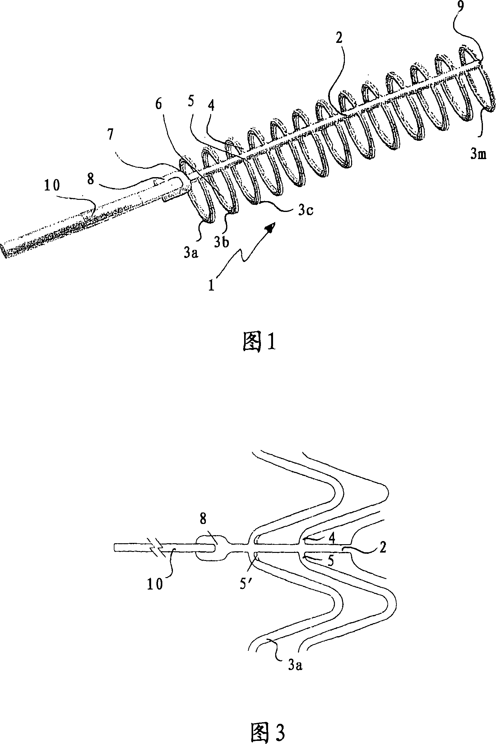
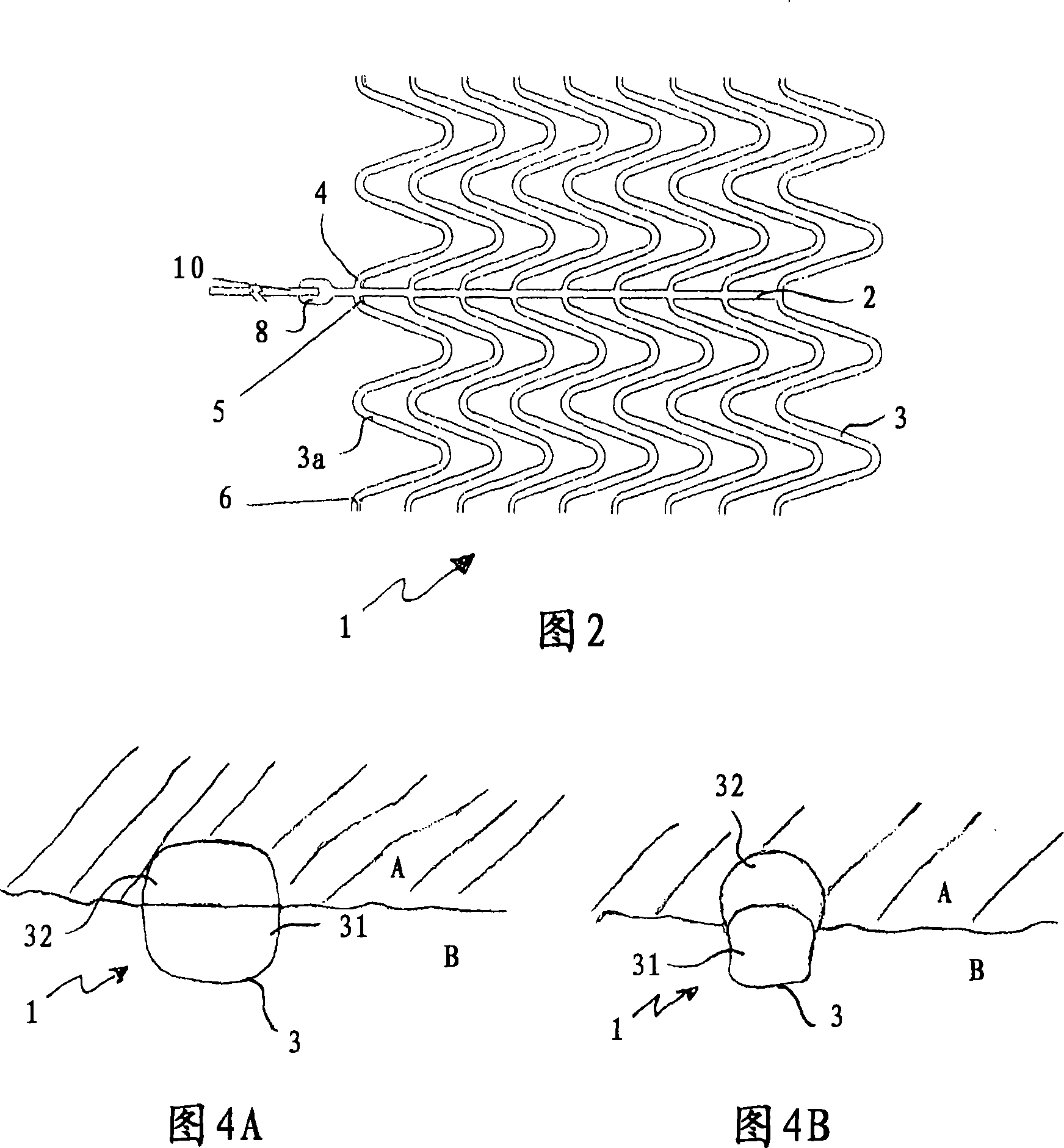
[0044] Figure 1 shows a temporary support 1 according to the invention with its spine 2 and individual ring segments 3a, 3b, 3c, ..., 3m in a fully expanded state, in which state each ring segment is expanded into a complete circle. The individual ring segments 3 a . Each ring segment 3 a . . . 3 m is substantially perpendicular to the spine 2 . The rib width of the ring segment 3 and of the spine 2 is approximately 50 μm, and the material thickness is likewise in the range of 50 μm.

[0045] Each of the ring segments 3 has three weakened areas, two of which 4, 5 are located next to the spine. A third weakened zone 6 is offset by 180° relative to the spine 2 , that is to say it lies opposite the spine 2 with respect to the ring segment. These weakened areas are established on each ring segment 3 . The weakened areas 4, 5, 6 are shown as areas of reduced rib width.

[0046] The spine 2 having a proximal end 7 and a distal end 9 has at its proximal end 7 a retrieval element...


PUM

PropertyMeasurementUnit
Wall thicknessaaaaaaaaaa

Abstract

The invention relates to a temporary stent, which has a multitude of adjacent ring elements and which can be explanted after having been implanted in a body lumen. All ring segments (3a, b, c, ) start from a spine (2) extending over the length of the stent (1) and have at least two weakened areas (4, 5, 6), which enable the ring segments (3a, b, c, ) to be folded when explanting the stent, and the spine (2) has a recovery element (8) at its proximal end (7), and the stent has two weakened areas (4,5) at two sides adjacent to the spine (2) and has a third weakened area (6) arranged 180 degrees offset to the spine (2). The invention also relates to a corona-stent with above characters.

Description

technical field [0001] The present invention relates to a temporary stent having a plurality of ring segments arranged along the length of the stent which can be removed again after implantation in a body lumen. In particular, the invention relates to a stent suitable for vascular, for example coronary or peripheral blood vessels, but can also be used for other body lumens with corresponding dimensions. Background technique [0002] Intraluminal stents are known in many application forms, which have a reduced diameter for delivery to the implantation site and which expand to the desired final diameter during the implantation process. Stents of this type are generally intended for durable implantation, ie they are intended to remain at the implantation site within the body. [0003] In many cases, however, the implanted stent loses its function after a certain duration; it has served its purpose, such as dilating the vessel, stabilizing a dysfunction, or closing a fistula or...

Claims


Application Information

Patent Timeline
IPC IPC(8): A61F2/86A61F2/90A61F2/82A61F2/844A61F2/88A61F2/91A61F2/915A61F2/95
CPCA61F2/915A61F2002/9528A61F2230/0054A61F2/844A61F2002/91533A61F2002/825A61F2002/91575A61F2/91
Inventor T·尼斯尔
Owner QUALIMED INNOVATIVE MEDIZINPROD
Why Eureka
Try Eureka