Jointing rod end protective cover with guiders

A technology of a guide and a protective cover, which is applied in the directions of fishing rods, fishing, and applications, can solve the problems such as the unsolved interference problem of the binding belt 109, and achieve the effect of easy installation work.

Active Publication Date: 2008-08-27
FUJI IND
View PDF0 Cites 1 Cited by
  • Summary
  • Abstract
  • Description
  • Claims
  • Application Information

AI Technical Summary

Problems solved by technology

If the cylindrical body 103 of the rod end protective cover 101 is simply lengthened, then in the installed state, it is a so-called complete set of the guide g of the cylindrical body 103, and the lockin

Method used


Image

  • Jointing rod end protective cover with guiders
  • Jointing rod end protective cover with guiders
  • Jointing rod end protective cover with guiders

Examples


Embodiment Construction

[0048] The jointed rod end protective cover 1 with a guide according to the first embodiment of the present invention will be described with reference to the drawings.

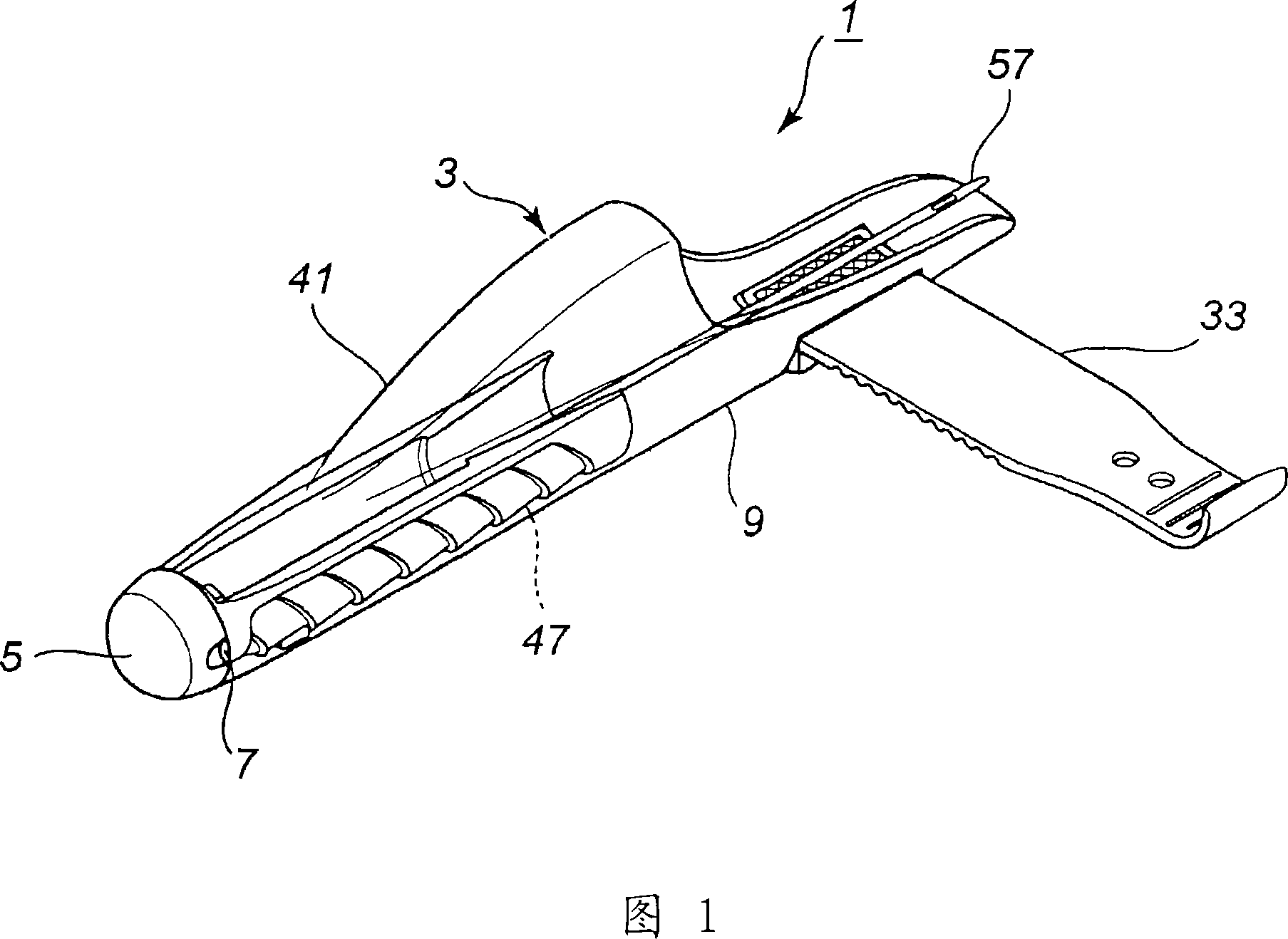
[0049] FIG. 1 shows a perspective view of a pole end protective sleeve 1 .

[0050] Reference numeral 3 denotes a transparent cylindrical sleeve body, the front port of which is plugged by being inserted with a cap 5 . Two vent holes 7 are formed on the cap 5 facing each other. The vent hole 7 communicates with the inner space of the sleeve body 3, and prevents corrosion of the guide and deterioration of the surface coating of the rod material due to moisture in the sleeve body 3.

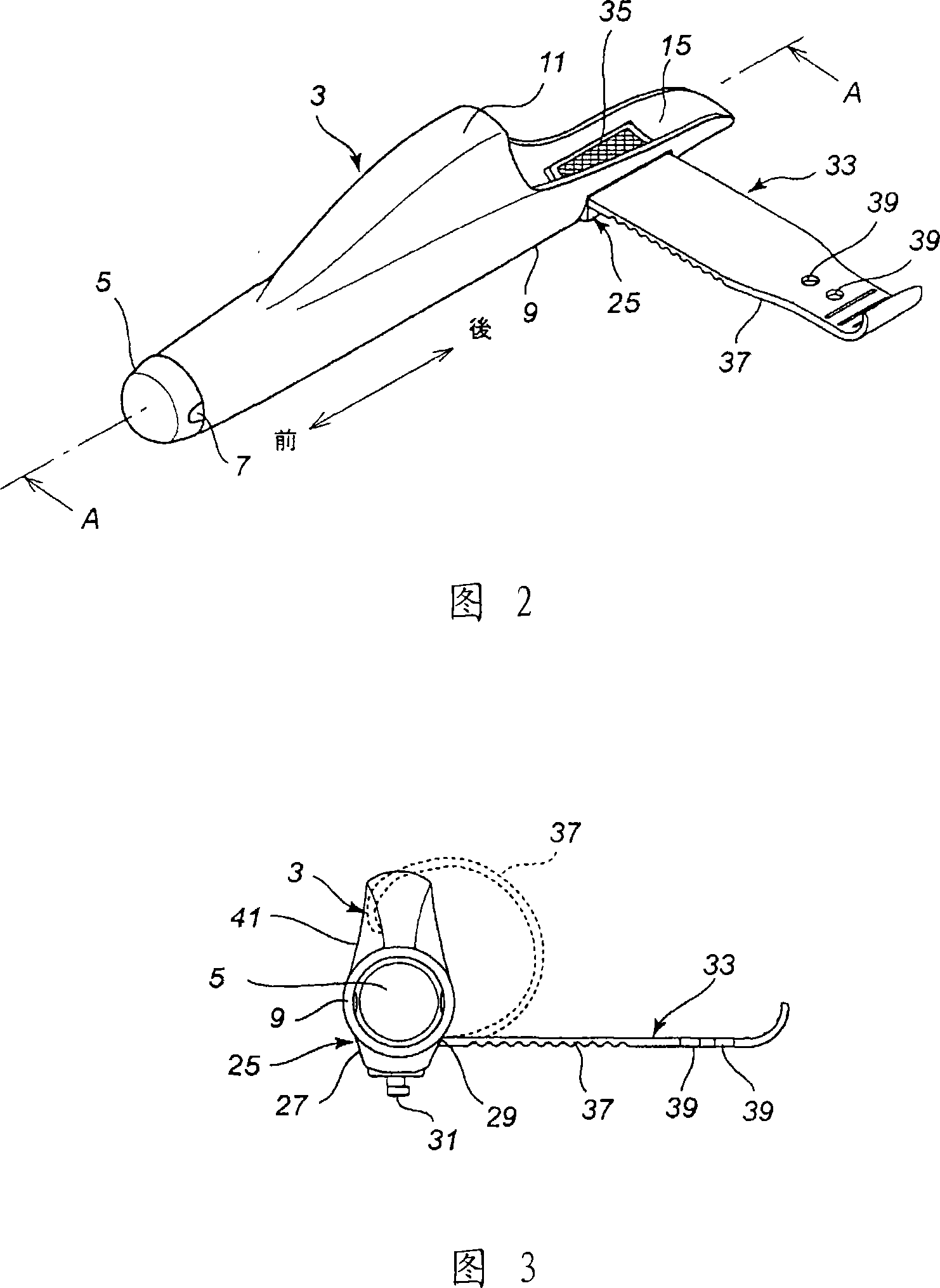
[0051] The cover body 3 is composed of a base part 9 and a cover part 41, and the base part 9 and the cover part 41 are integrally formed into a cylindrical shape by resin molding of a single part.

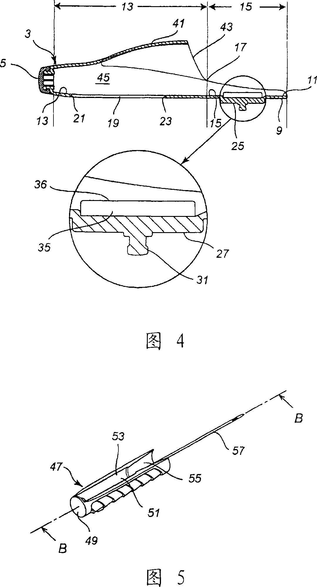
[0052] Reference numeral 47 denotes a locking block, and the locking block 47 is inserted and accommodated in the case body 3 .

...


PUM


Abstract

A jointing rod end protective sleeve with a guide is disclosed, the subject to be solved is that, the guide is exposed upwardly at rear side of the current rod end protective sleeve which is able to freely slide a stop block, if a long sleeve is added singly to form a total sleeve, the entire structure is enlarged and inconvenient. When being installed, an angler whose hands are in normal size only holds the sleeve with one hand while using fingers to press the stop block for inhibiting the advance, either way, the binding belt is not pressed. Accordingly, the coiled binding belt makes the protective sleeve more inconvenient. The solution is that, in terms of length of current extending cover part (41) and at the time of pulling out the stop block (47) backwardly to a maximum extent, the protective sleeves is designed to locate upon a root (35) of the binding belt (33) from the back end thereof, thus adjusting the entire length.

Description

technical field [0001] The invention relates to a jointing rod end protection sleeve with a guide. Background technique [0002] Fig. 15 is a jointed rod end protector 101 with a guide of a conventional product (Patent Document 1). [0003] The rod end protector 101 holds a locking block 107 on which the rod end t is attached so as to be slidable in the front and rear directions in the cylindrical body 103 . [0004] When the rod end protector 101 is used, even when the locking block 107 is pressed to the front side of the cylindrical body 103 to the maximum, some of the plurality of guides g installed on the rod end t are located in the notch 105 On the top, it is exposed upward, and the exposed state is unstable in terms of strength depending on the type of guide g. [0005] The reason why the locking block 107 adopts free sliding is that the rod end can be easily and reliably installed on the locking block 107 without damage by pulling the locking block 107 out from the...

Claims


Application Information

Patent Timeline
IPC IPC(8): A01K87/00A01K87/02
Inventor 大村一仁
Owner FUJI IND
Why Eureka
Try Eureka