
Large-scale injection machine

An injection molding machine and large-scale technology, applied in the field of solid rubber injection molding machines, can solve the problems of low production efficiency and unstable product quality of flat vulcanizers, and achieve the effects of good compactness, uniform density and reduced labor intensity.

Inactive Publication Date: 2008-08-27
HENGYANG HUAYI MACHINERY
View PDF0 Cites 6 Cited by
  • Summary
  • Abstract
  • Description
  • Claims
  • Application Information

AI Technical Summary

Problems solved by technology

[0003] The purpose of the present invention is to overcome the above-mentioned deficiencies of the prior art and provide a new type of large-scale rubber injection molding machine to solve the problem that the existing injection molding machine can only produce small and medium-sized products and the low production efficiency and poor product quality of the flat vulcanizing machine. stability problem

Method used


Image

  • Large-scale injection machine
  • Large-scale injection machine
  • Large-scale injection machine

Examples


Embodiment Construction

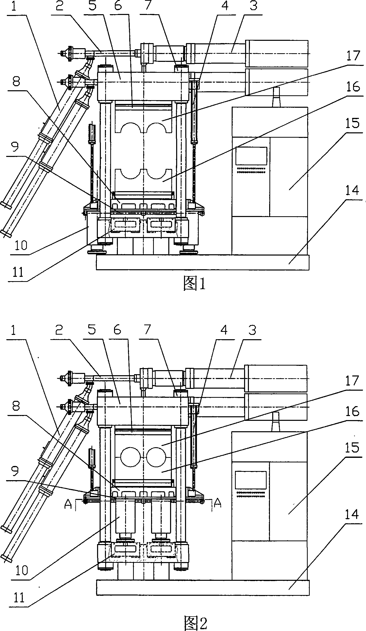
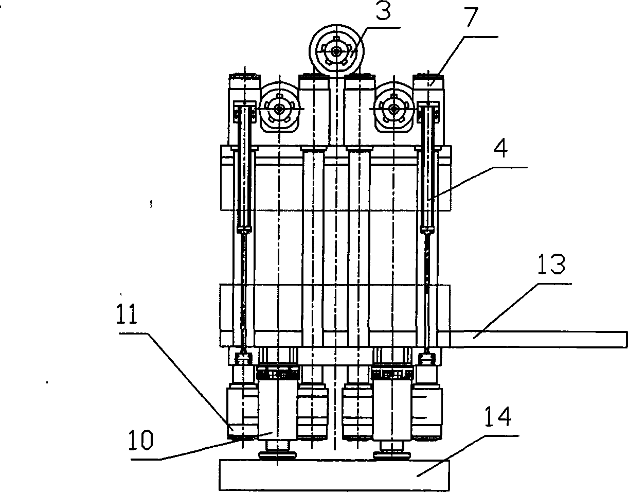
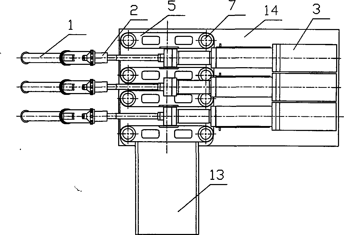
[0024] As shown in the attached figure: a large injection molding machine, which includes three feeding devices 1, three plasticizing devices 2, three injection devices 3, four clamping cylinders 4, two upper templates 5, and cold runners 6. Eight Corinthian pillars 7. Moving template 8. Four pad guide rails 9. Four moving pads 10. Four clamping cylinders 11. Four pad cylinders 12. Mold moving device 13. Base 14. Control System 15 , lower die 16 and upper die 17 .

[0025] The control system 15 is installed on the base 14, and the three injection devices 3 are placed on the upper part of the control system 15 and the upper template 5. The three injection devices 3 are arranged in the shape of a letter along the length direction of the mold, and each injection device is equipped with a plasticizing device. 2 and a feeding device 1.

[0026] The four clamping oil cylinders 11 of the mold clamping part are arranged in a square shape, and the two mold clamping cylinders 11 have a...


PUM


Abstract

A major injection molding machine comprises a control system mounted on a base, and three injecting devices positioned above a control system and an upper mold plate and arranged in the shape of Chinese character Pin along the length direction of a mold. Each injecting device is provided with a plasticizing device and a feeding device; four mode-locked oil cylinders in a mode-locked part are arranged in a quadrangle shape, wherein, every two mode-locked oil cylinders share one cylinder body; eight tie bars are divided into two parts and respectively connected onto the cylinder body of a mode-locked oil cylinder and an upper mold plate; a moveable mold plate arranged between the upper mold plate and the cylinder body of the mode-locked oil cylinder slides up and down along a guide rail formed by the eight tie bars; a cold runner is fixed on the upper mold plate; the base of a mold stripping device is fixed on the moveable mold plate; four moveable cushion blocks and cushion block oil cylinders are connected under the moveable mold plate through the rail formed by the eight tie bars. The mold is divided into an upper mold and a lower mold, wherein the upper mold in fixed on the cold runner, and the lower mold is connected with the sliding plate of the mold stripping device.

Description

technical field [0001] The invention relates to a solid rubber injection molding machine. Background technique [0002] In the prior art, there are two ways to form solid rubber products: one is to use injection molding for small and medium-sized products, and the injection molding machine currently used has at most two sets of injection devices, and each set of injection devices is limited by the size and strength of steel. , Hydraulic oil pressure and other factors, the injection volume is limited, so it is only suitable for small and medium-sized products. For larger products, it cannot be molded at one time due to insufficient injection volume; the second is to use a flat vulcanizing machine to make large products. The flat vulcanizing machine does not have an injection device, it is manually placed the solid rubber directly into the mold cavity, and the pressure generated by locking the two halves of the mold with the clamping machine makes the rubber fill the entire mo...

Claims


Application Information

Patent Timeline
IPC IPC(8): B29C45/13B29C45/67
Inventor 都兴武
Owner HENGYANG HUAYI MACHINERY
Learn More