Seal structure body and sealing method of liquid leading-out portion, fluid vessel, re-filling fluid vessel and re-filling method thereof

A technology of sealing structure and fluid container, applied in printing, printing device and other directions, can solve problems such as damage to the seal, ink leakage, and elastic seal damage of the sealing member and the inner wall of the ink passage.

Active Publication Date: 2008-08-27
SEIKO EPSON CORP
View PDF4 Cites 9 Cited by
  • Summary
  • Abstract
  • Description
  • Claims
  • Application Information

AI Technical Summary

Problems solved by technology

[0008] However, for example, when the accuracy of the roundness of the ink passage of the ink outlet part deteriorates, the elastic seal between the sealing member and the inner wall of the ink passage will become incomplete, and ink leakage will occur.
In addition, when the ink is supplied by pressurization as described in Patent Document 1, if the elastic seal between the sealing member and the inner wall of the ink passage is weak, the pressure-fed ink may break the seal.
Also, when the ink cartridge is dropped or vibration is applied to the ink cartridge, the elastic seal between the sealing member and the inner wall of the ink passage may be temporarily broken.
[0009] This problem is not limited to ink cartridges, and the same problem occurs in various uses of the type that elastically seals between the inner wall of the fluid passage formed on the fluid outlet part and the sealing member.

Method used


Image

  • Seal structure body and sealing method of liquid leading-out portion, fluid vessel, re-filling fluid vessel and re-filling method thereof
  • Seal structure body and sealing method of liquid leading-out portion, fluid vessel, re-filling fluid vessel and re-filling method thereof
  • Seal structure body and sealing method of liquid leading-out portion, fluid vessel, re-filling fluid vessel and re-filling method thereof

Examples


no. 1 approach

[0061] Next, preferred embodiments of the present invention will be described in detail. The present embodiment described below is not intended to unduly limit the content of the present invention described in the claims, and all the components described in the present embodiment are not essential as the solution means of the present invention. .

[0062] (Outline of Fluid Ejection Device)

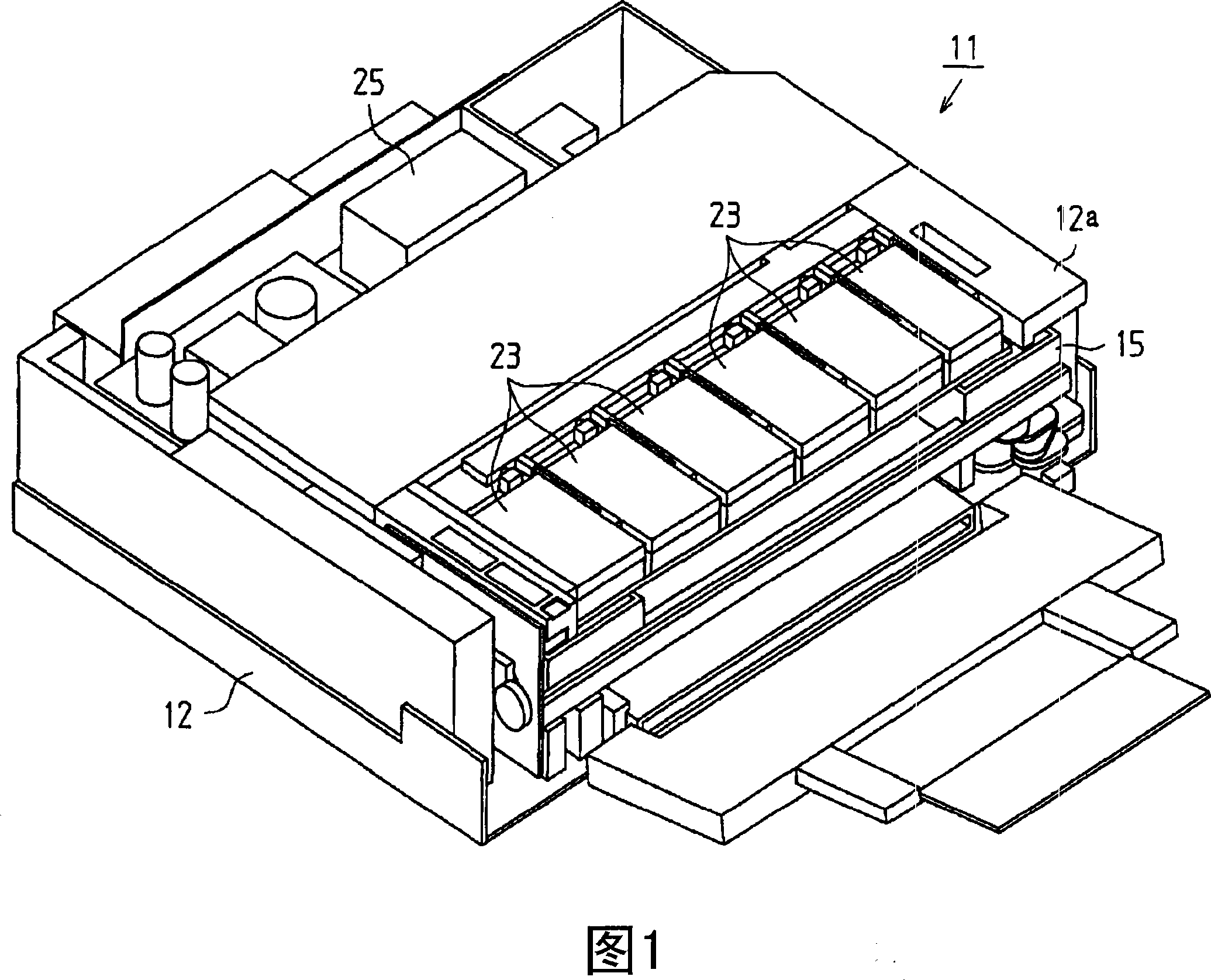
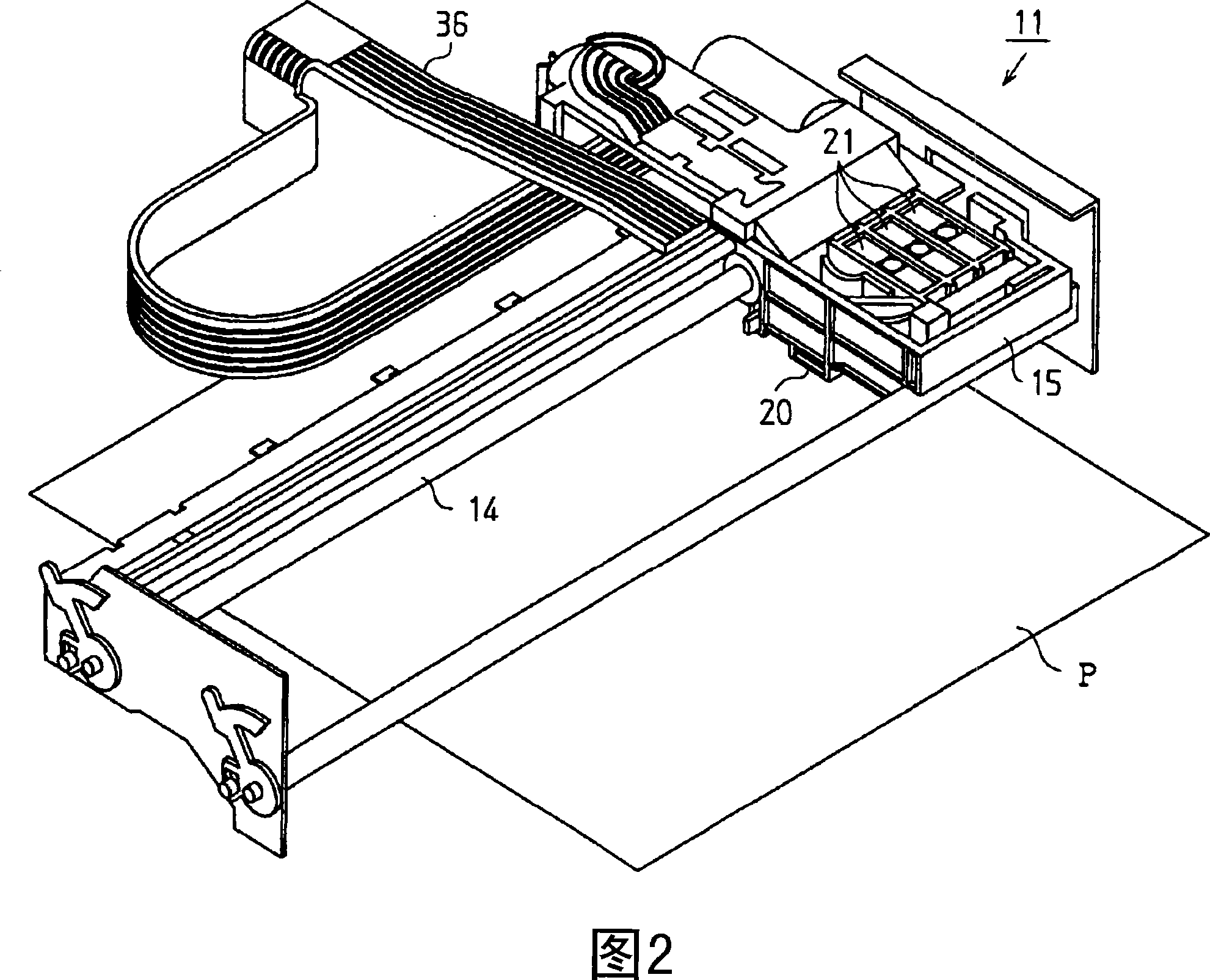
[0063] As shown in FIG. 1 , a printer 11 as a fluid ejection device according to this embodiment is covered by a frame 12 . And, as shown in FIG. 2, a guide shaft 14, a carriage 15, a recording head 20 as a liquid ejection head, a valve unit 21, an ink cartridge 23 (refer to FIG. Pump 25 (see FIG. 1 ).

[0064] As shown in FIG. 1, the frame 12 is a box approximately in the shape of a rectangular parallelepiped, and an ink cartridge holder 12a is formed on the front thereof.

[0065] As shown in FIG. 2 , the guide shaft 14 is formed in a rod shape and is spanned within the frame body 12...

no. 2 approach

[0110] FIG. 6 is an exploded perspective view of an ink outlet unit 50 different from that of the first embodiment. The external shape of the ink outlet part 50 shown in FIG. 6 is different from the ink outlet part 32b of the first embodiment. In addition, in the present embodiment, the sealing film F2 is not welded to the ink case, but is only welded to the ink outlet portion 50 and the sealing member 60 . This embodiment differs from the first embodiment only in the above points, and is the same as the first embodiment in other points.

[0111] 7 is a partial cross-sectional view showing a state before the sealing member 60 is inserted into the ink outlet 51 and the sealing film F2 is thermally welded.

[0112]The ink outlet portion 50 has an annular first weldable portion 54 protruding by a height L from the opening end surface 53 . Similarly, the sealing member 60 has an annular second weldable portion 62 that protrudes by a height L relative to the opening end surface 5...

no. 3 approach

[0117] A third embodiment will be described using FIGS. 8 to 14B . In this embodiment, the configuration of an ink cartridge serving as a fluid container is different from that of the first embodiment. The ink cartridge of this embodiment can be mounted on the same fluid ejection device as that described in the first embodiment. Therefore, a detailed description of the fluid ejection device will be omitted.

[0118] 8 is an exploded perspective view of an ink cartridge which is an embodiment of the fluid container according to the third embodiment. FIG. 8 is a perspective view of the state in the bag housing portion of the container main body, FIG. 9B is an enlarged view of part A of FIG. 9A , and FIG. 10 is an exploded perspective view of the liquid remaining amount detection unit shown in FIG. 8 .

[0119] In addition, FIG. 11 is an assembled perspective view of the remaining liquid amount detection unit, and FIG. 12 is a perspective view of the remaining liquid amount det...


PUM


Abstract

The present invention provides a fluid-outlet-section sealing structure that includes: a fluid outlet section, a sealing member, and a sealing film. The fluid outlet section has a fluid flow channel and an open-end surface. The open-end surface of the fluid outlet section is formed at a fluid outlet end of the fluid flow channel of the fluid outlet section. The sealing member is provided in the fluid flow channel of the fluid outlet section. The sealing film is provided to cover the fluid flow channel of the fluid outlet section and the open-end surface of the fluid outlet section. The sealing film is thermally adhered to the open-end surface of the fluid outlet section and the sealing member.

Description

technical field [0001] The present invention relates to, for example, a sealing structure and a sealing method of a fluid outlet suitable for an ink cartridge for a printer, a fluid container, a refilling fluid container, and a refilling method thereof. Background technique [0002] Conventionally, there is an inkjet printer as a liquid ejecting device that ejects liquid droplets from nozzles of a liquid ejecting head. Some inkjet printers have an off-carriage ink supply system that loads the ink cartridges in a location other than the carriage. As a case of having such an off-carriage type ink supply system, there are, for example, the case of having a large-capacity ink cartridge for large-format printing, and the miniaturization and thinning of an inkjet printer by reducing the size of the carriage by not loading an ink cartridge. situation etc. [0003] In such an off-rack type ink supply system, for example, the ink cartridge is arranged on the side of the main body. ...

Claims


Application Information

Patent Timeline
Patent Type & Authority Applications(China)
IPC IPC(8): B41J2/175
CPCB41J2/17596B41J2/17513B41J2/17509Y10T29/49401B41J2/1752B41J2/17553B41J29/00
Inventor 青木雄司木村仁俊野泽泉
Owner SEIKO EPSON CORP
Why Eureka
Try Eureka