Enclosing-suction type combined kitchen tool

A technology of kitchen utensils and suction ports, which is applied in the field of surrounding suction combined kitchen utensils, which can solve the problems of wasting power, unhygienic, and moisture-prone items, and achieve the effects of good oil fume absorption, high cost performance, and novel design

Inactive Publication Date: 2008-08-27
陈安华
View PDF0 Cites 0 Cited by
  • Summary
  • Abstract
  • Description
  • Claims
  • Application Information

AI Technical Summary

Problems solved by technology

This kind of setting has some merits, but the disadvantage is that it is bulky and the oil fume pollution area in the frame is large. The locker or disinfection cabinet is set under the gas stove and the front is too close to the ground, and the items are easy to be damp and unhygienic.
Due to the large size of this kind of cabinet-type cooker, it cannot be used as a cooker with an ordinary gas cooker, and it is inconvenient to install, and it is not possible to shut down the suction port of another stove when a single stove is used for cooking. Can not be shut down, resulting in waste of power

Method used


Image

  • Enclosing-suction type combined kitchen tool
  • Enclosing-suction type combined kitchen tool
  • Enclosing-suction type combined kitchen tool

Examples


Embodiment approach 1

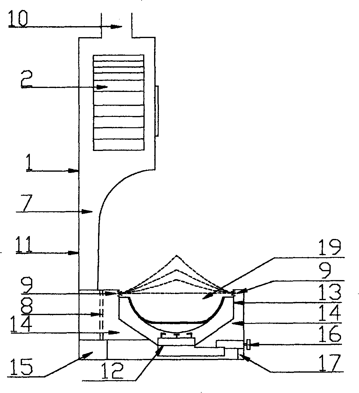
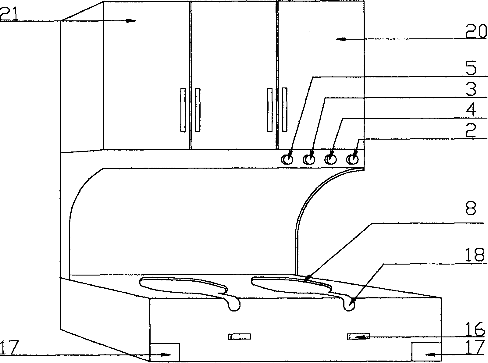
[0015] Implementation Mode 1: According to figure 1 , image 3 As shown, the fan is located on the top or rear of the gas cooker. Frame 1 is provided with blower fan 2, motor, control regulator and other supporting settings (not shown in the figure), and there is oil fume passage 7 connected with gas stove oil fume passage 14; Body middle part front is provided with power switch 2, left wind force key 3, right wind force key 4, delay key 5 and light key, is provided with disinfection cabinet 20, locker 21 beside fan frame body, also can establish a decorative plate to blow fan Outer frame and exhaust pipe cover. The inner bottom of the circular concave wall 13 of the gas stove frame 11 is processed with a combustion cooker 12, and the upper edge of the circular concave wall 13 is processed with ring-shaped suction ports 9, and the oil storage box 15 is arranged on both sides of the gas stove frame. Box drawer face 17 is processed in frame body front bottom, and its front to...

Embodiment approach 2

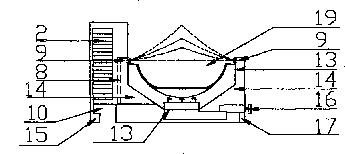
[0016] Implementation mode two: according to figure 2 , Figure 4 shown, with figure 1 , image 3 The main difference is: the wind wheel 2 is arranged at the rear position of the gas stove; the oil smoke outlet 10 is processed at the lower end of the oil smoke device, which is a lower row type. The height ratio between the range fume device and the gas stove of this style can be changed to a variety of styles, and can also be set to side row, rear row, top row and other styles [not shown in the figure], and can also be used on the gas stove A device protruding forward is provided with one or more suction ports on the lampblack device higher than a certain ratio. The rear row type can be set as a style that directly discharges the oil fume out of the wall. In this style, the oil fume device can also be installed in whole or in part in the window or wall near the back of the gas stove to reduce the placement area of ​​the gas stove. This style also can be when the range fum...


PUM


Abstract

The present invention relates to an encompass-suction type combined cookware, which is formed by combining an oil fume suction device and a gas range. The oil fume suction device is arranged on the rear side or upper side of the gas range. One or more than one wind wheel and oil fume channel is arranged on the oil fume suction device. The channel is communicated with a suction inlet which surrounds a pan body via the oil fume channel inside a gas range frame. The suction inlet is capable of sucking smoke by two or more than two range suction inlets synchronously or by single range suction inlet. The encompass-suction type combined cookware can be downward arranged, backward arranged, laterally arranged or upward arranged, and can be combined into a plurality of styles. The cookware has the advantages of novel design, power saving, practicality, good oil fume suction performance, fashion and good appearance.

Description

technical field [0001] The invention relates to a kitchen appliance, in particular to a suction-surrounding combined kitchen utensil. Background technique [0002] Existing and various range hood combined gas ranges of published patent documents, the range hood device is generally all arranged under the gas range, and the oil smoke type is discharged downwards, and the lower front is provided with a frame locker or a disinfection cabinet. This kind of arrangement has certain merits, but the disadvantage is that it is bulky, and the oil fume pollution area in the frame is large. The locker or disinfection cabinet is set too close to the ground in front of the gas stove, and the items are easy to be damp and unhygienic. Due to the large size of this kind of cabinet-type cooker, it cannot be used as a cooker with an ordinary gas cooker, and it is inconvenient to install, and it is not possible to shut down the suction port of another stove when a single stove is used for cookin...

Claims


Application Information

Patent Timeline
Patent Type & Authority Applications(China)
IPC IPC(8): F24C15/20
Inventor 陈安华
Owner 陈安华
Why Eureka
Try Eureka