Switching regulator

A switching regulator and switching technology, applied in instruments, output power conversion devices, DC power input conversion to DC power output, etc., can solve problems such as low efficiency, reverse current generation, and no consideration of input voltage and voltage changes, etc. Achieve the effect of improving efficiency and preventing reverse current

Inactive Publication Date: 2008-08-27
RICOH KK
View PDF2 Cites 18 Cited by
  • Summary
  • Abstract
  • Description
  • Claims
  • Application Information

AI Technical Summary

Problems solved by technology

However, the voltage change of the input voltage Vin is not considered for the reference voltage applied to the comparator for reverse current detection

Method used


Image

  • Switching regulator
  • Switching regulator
  • Switching regulator

Examples


no. 1 example

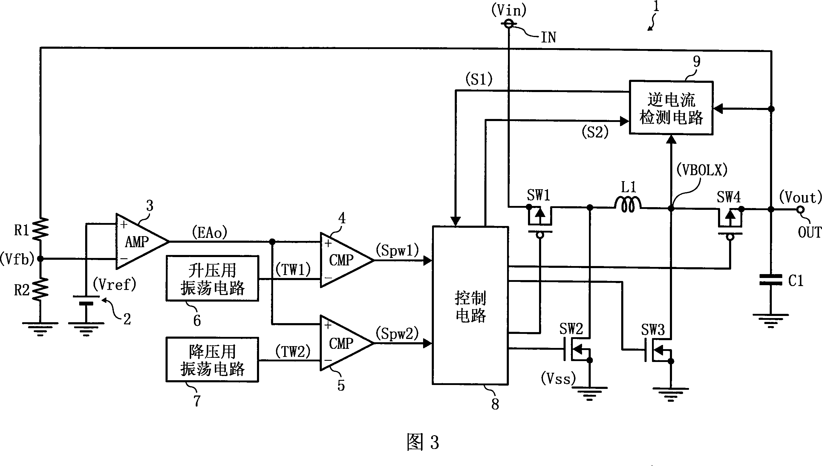
[0057] FIG. 3 shows a circuit example of the buck-boost switching regulator according to the first embodiment of the present invention.

[0058] In Fig. 3, the buck-boost switching regulator 1 inputs the input voltage Vin to the input terminal IN, and converts the input voltage Vin into a set constant voltage as an output The voltage Vout is output from the output terminal OUT.

[0059] The buck-boost switching regulator 1 includes an inductor L1, a step-down switching transistor SW1, a step-down synchronous rectification transistor SW2, a step-up switching transistor SW3, and a step-up synchronous rectification transistor SW4. The step-down switching transistor SW1 is composed of a PMOS transistor, and switches for a step-down operation according to an input control signal, and charges the inductor L1 from the input voltage Vin. The step-down synchronous rectification transistor SW2 is composed of Composed of NMOS type transistors, the switch for the step-down operation is i...


PUM


Abstract

The invention relates to a switch voltage stabilizer. A reverse current detection circuit (9) compares the voltage difference between the output voltage (Vout) and the voltage (VBOLX) with a reference voltage generated in the reverse current detection circuit (9). If the voltage difference is lower than the reference voltage, a preset reverse current detection signal (S1) is output to a control circuit (8) to break the synchronous commutation transistor SW4 for boosting pressure to be a cutoff state, and the reverse current is prevented. The switch voltage capable of prevent reverse current generation in diverse action mode is obtained.

Description

technical field [0001] The present invention relates to a switching regulator provided with a reverse current prevention circuit. More specifically, the reverse current prevention circuit corrects the difference in detection voltage for detecting reverse current in a step-up operation and a step-down operation. , can improve the power conversion efficiency. Background technique [0002] In conventional synchronous rectification switching regulators, there are continuous mode in which the current flows continuously to the inductor and discontinuous mode in which the current flowing in the inductor is not continuous. The so-called reverse current is generated when the current flows in the reverse direction toward the inductor at the output terminal, and the power conversion efficiency is obviously low. [0003] FIG. 1 shows a circuit example of a conventional step-down switching regulator provided with a reverse current prevention function (for example, refer to Patent Docume...

Claims


Application Information

Patent Timeline
IPC IPC(8): H02M3/156
CPCH02M3/1582H02M3/155
Inventor 西田淳二
Owner RICOH KK
Why Eureka
Try Eureka