Switching power supply circuit

a power supply circuit and circuit technology, applied in the direction of electric variable regulation, process and machine control, instruments, etc., can solve the problems of increasing power loss, rectification current on the secondary side showing discontinuous mode, and limited improvement of power conversion efficiency of switching converters, so as to achieve simple circuit configuration and free from increasing loss by reactive power

Inactive Publication Date: 2005-03-31
SONY CORP
View PDF8 Cites 60 Cited by
  • Summary
  • Abstract
  • Description
  • Claims
  • Application Information

AI Technical Summary

Benefits of technology

It is an object of the present invention to provide a switching power supply circuit which is simple in circuit configuration and is free from increase of the loss by reactive power.
Further, the inductor element inserted in the secondary side rectification current path can suppress reverse directional current appearing in the rectification current. Consequently, further reduction of the reactive power can be anticipated.

Problems solved by technology

Further, it is known that the switching converters are limited in improvement in the power conversion efficiency from their operation characteristics.
However, in a condition wherein the load is in a heavy load tendency in a compatible load power range, the rectification current on the secondary side exhibits a discontinuous mode.
Further, since the voltage drop in the forward direction of the rectification diodes Do1, Do2 which are Schottky diodes is 0.6 volts and, in such operation of the secondary side as described above, the rectification currents I1, I2 exhibit a considerably high level of 35 Ap, the continuity loss by the rectification diodes appears conspicuously, resulting in increasing power loss.
If current flows in the reverse direction, then discharge current flows from the smoothing capacitor Co to the insulating converter transformer PIT side, and therefore, power cannot be transmitted efficiently to the load side.
Further, the reverse current gives rise to generation of heat by the MOS-FET or to production of noise and also to switching loss on the primary side.
In this manner, where the synchronous rectification circuit employs the winding voltage detection system, although the continuity loss of rectification current decreases, since reactive power is generated in such a manner as described above, it is generally difficult to achieve effective improvement of the power conversion efficiency.
In this manner, also the power supply circuit of the configuration wherein the secondary side rectification circuit system is replaced by the synchronous rectification circuit according to the winding voltage detection method still has the problem of a drop of the power conversion efficiency upon the heavy load operation.
Consequently, the circuit configuration is complicated, and this gives rise to a disadvantage in that it causes drop of the production efficiency, increase of the cost, expansion of the size of a circuit board and so forth.
Accordingly, two sets of such a current transformer and a drive circuit system as described above are required individually corresponding to the MOS-FETs Q3, Q4, and this makes the problem described above further serious.

Method used


Image

  • Switching power supply circuit
  • Switching power supply circuit
  • Switching power supply circuit

Examples


first embodiment

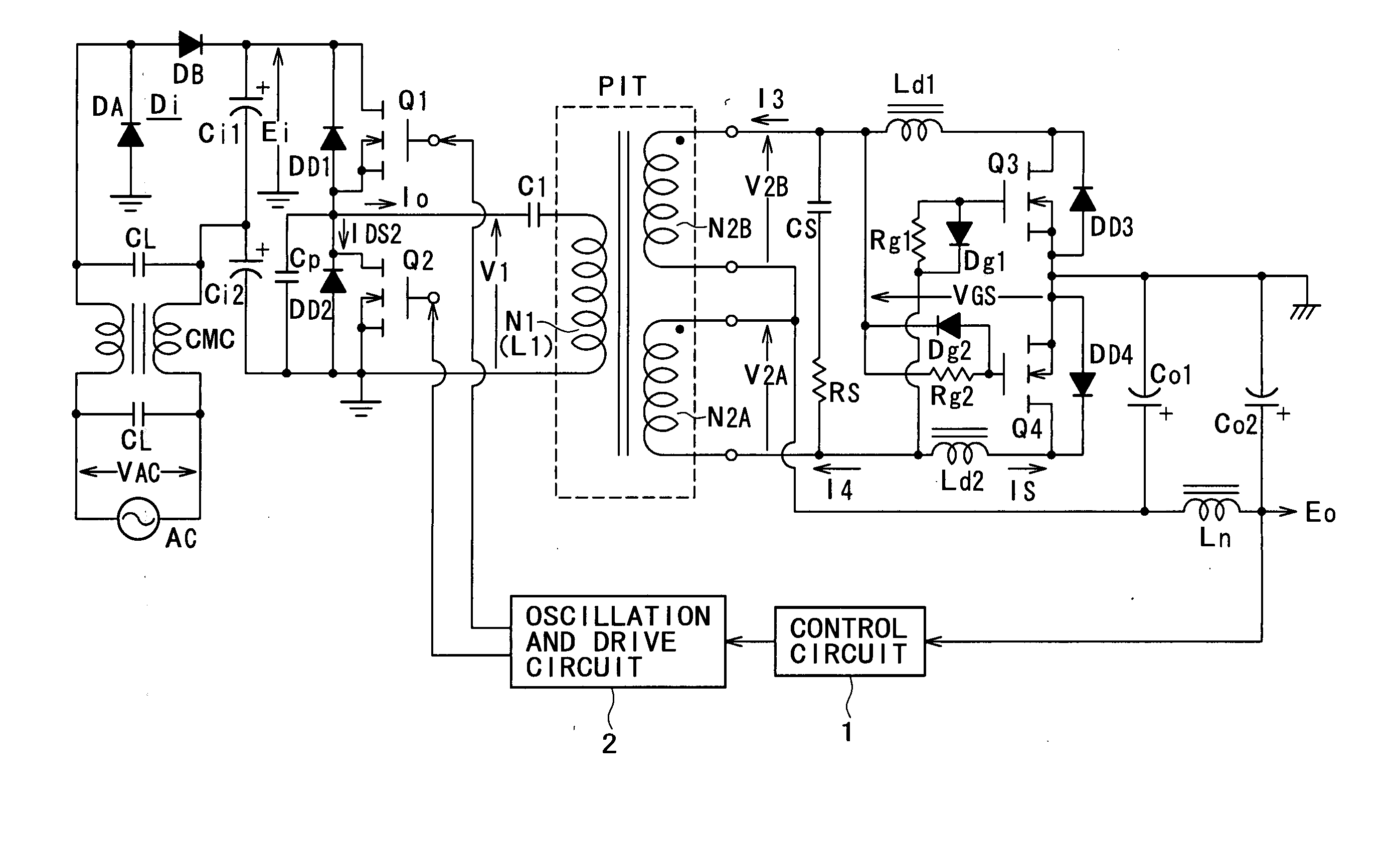
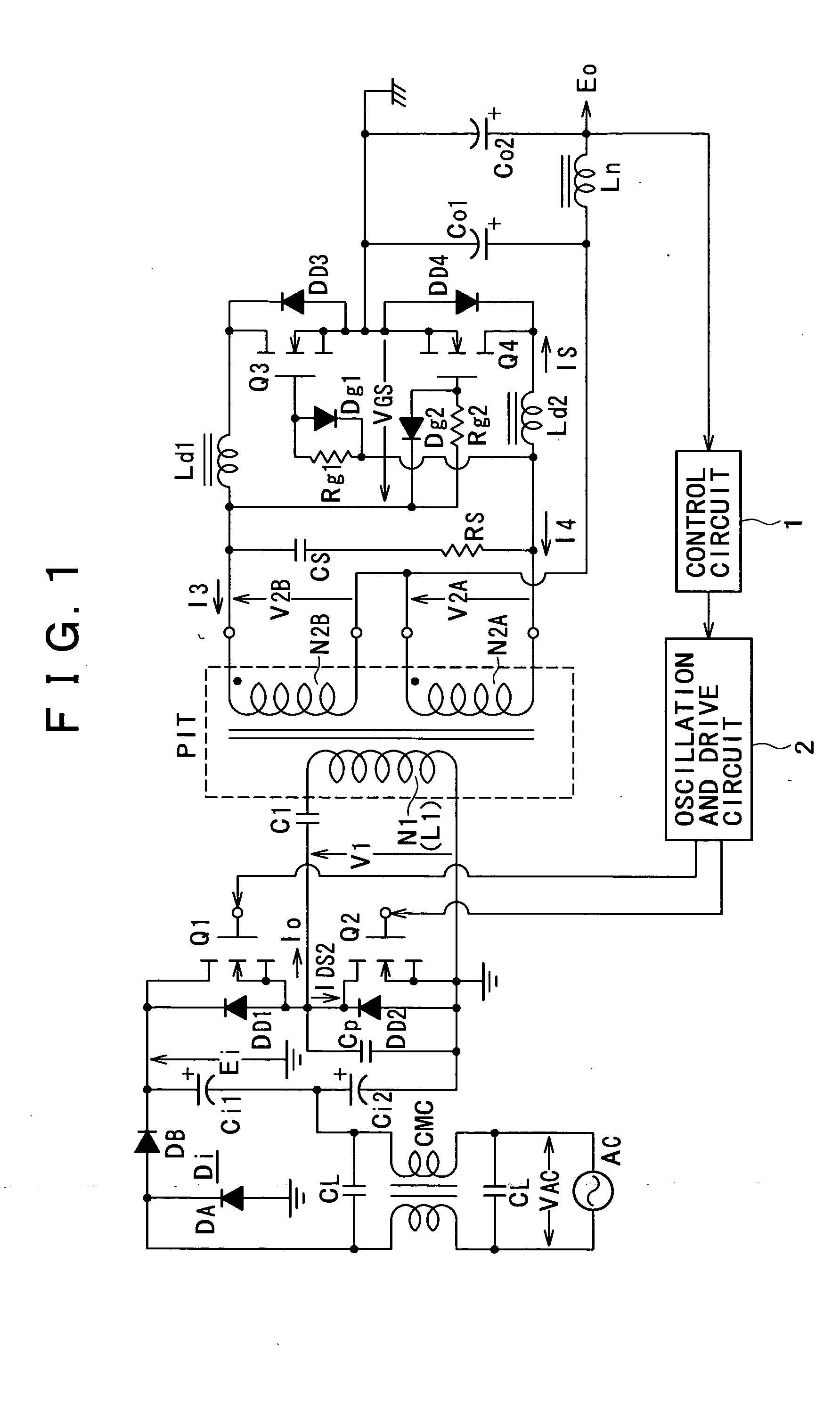
FIG. 1 shows a basic configuration of a switching power supply circuit to which the present invention can be applied and on which the present invention hereinafter described is based. The power supply circuit is generally configured such that it includes, as a basic configuration of the primary side, a combination of a partial voltage resonance circuit with a current resonance converter according to a half bridge coupling system of the separately excited type.

In the power supply circuit shown in FIG. 1, a noise filter is formed from a pair of filter capacitors CL and a common mode choke coil CMC for a commercial ac power supply AC.

A voltage doubler rectification circuit is connected as a succeeding stage of the noise filter and includes a rectification circuit section Di formed from rectification diodes DA, DB and two smoothing capacitors Ci1, Ci2. The voltage doubler rectification circuit produces a level rectified smoothed voltage Ei (dc input voltage) corresponding to twice th...


PUM

PropertyMeasurementUnit
equivalent series resistanceaaaaaaaaaa
voltage withstandingaaaaaaaaaa
inductanceaaaaaaaaaa

Abstract

A switching power supply circuit is disclosed which can achieve a high power conversion efficiency and besides achieve reduction of the circuit scale and the cost by simplification in circuit configuration. The switching power supply circuit includes a synchronous rectification circuit of the winding voltage detection system on the secondary side of a resonance converter. The coupling coefficient of an insulating converter transformer or the induced voltage level per one turn of the secondary winding is set so that the magnetic flux density of the insulating converter transformer may be lower than a fixed level thereby to maintain the secondary side rectification current in a continuous mode even in a heavy load condition. An inductor is inserted in series in a path along which rectification current is to be supplied to a secondary side smoothing capacitor so that reverse current appearing on the rectification current is suppressed by counter electromotive force generated in the inductor to further reduce the reactive power. A dc superposition characteristic of the inductor is set so that abnormal oscillation in a very light load condition (for example, 12.5 W or less) is prevented.

Description

BACKGROUND OF THE INVENTION This invention relates to a switching power supply circuit incorporated as a power supply in various electronic apparatus. Various switching power supply circuits are widely known including, for example, a switching power supply circuit of the flyback converter type or the forward converter type. The switching converters of the types mentioned are restricted in suppression of switching noise because the switching operation waveform is a rectangular waveform. Further, it is known that the switching converters are limited in improvement in the power conversion efficiency from their operation characteristics. Therefore, various switching power supply circuits which use a resonance converter have been proposed and placed into practical use. The resonance converters are advantageous in that a high power conversion efficiency can be achieved readily and low noise can be achieved because the switching operation waveform thereof is a sine waveform. The resonan...

Claims


Application Information

Patent Timeline
Patent Type & Authority Applications(United States)
IPC IPC(8): H02M7/21H01F30/04H01F38/08H02M3/28H02M3/335
CPCH01F30/04H01F38/08H01F2019/085Y02B70/1491H02M3/33592Y02B70/1475H02M2001/0058H02M3/33569Y02B70/10H02M1/0009H02M1/0058H02M3/33571H02M3/01H02M3/28
Inventor YASUMURA, MASAYUKI
Owner SONY CORP
Why Eureka
Try Eureka