
Step down switching regulator with the substrate of the switching transistor selectively connected to either its drain or source

a switching regulator and substrate technology, applied in secondary cell servicing/maintenance, process and machine control, instruments, etc., can solve the problems of high power loss in a circuit, degrade the efficiency of the power supply, and degrade the power efficiency

Active Publication Date: 2008-01-15
RICOH KK
View PDF20 Cites 61 Cited by
  • Summary
  • Abstract
  • Description
  • Claims
  • Application Information

AI Technical Summary

Benefits of technology

The present invention provides a switching regulator that can prevent reverse direction flow of electric current without using a dedicated diode, even when a PMOS transistor is used as a switching element. This is achieved by a selection circuit that connects the substrate gate of the switching transistor to either the drain or source of the transistor based on the input control signal. The selection circuit can also control the connection of the substrate gate based on the voltage on the input terminal. The invention also includes a smoothing circuit and a control circuit for the switching transistor. The technical effects of the invention include improved efficiency and reduced size of the switching regulator, as well as improved performance and reliability of the power supply circuit.

Problems solved by technology

The reverse direction flow not only degrades efficiency of the power supply, but also causes a crash or a malfunction of the power supply circuit; hence, it is necessary to prevent the reverse direction flow.
This may cause high power loss in a circuit for supplying a large current, and degrade the power efficiency.
However, when increasing the difference between the input voltage and the output voltage, the power efficiency degrades, and when using the high output voltage source, the circuit turns out to be complicated and becomes expensive.

Method used


Image

  • Step down switching regulator with the substrate of the switching transistor selectively connected to either its drain or source
  • Step down switching regulator with the substrate of the switching transistor selectively connected to either its drain or source
  • Step down switching regulator with the substrate of the switching transistor selectively connected to either its drain or source

Examples


Embodiment Construction

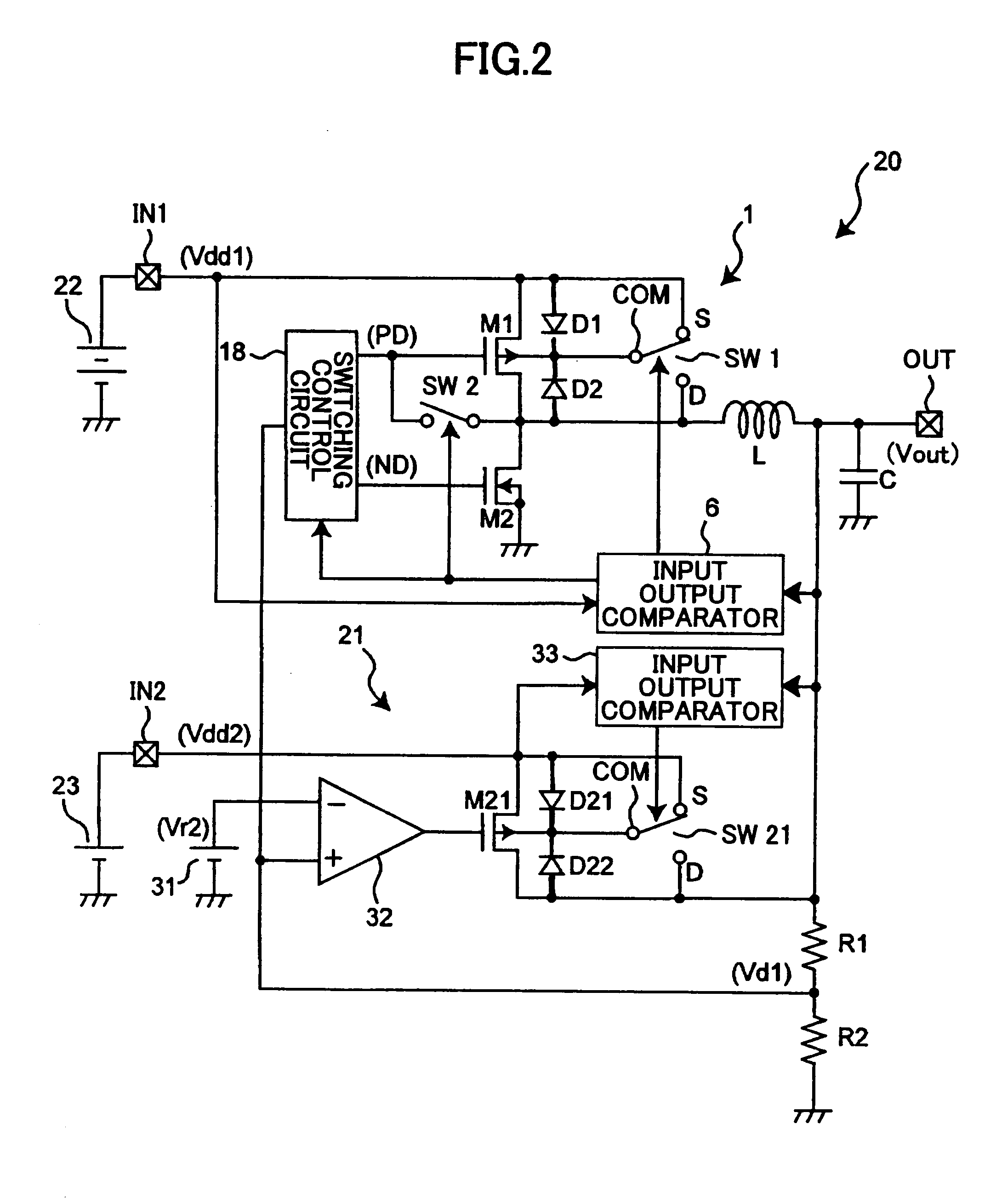
[0053]Below, preferred embodiments of the present invention are explained with reference to the accompanying drawings.

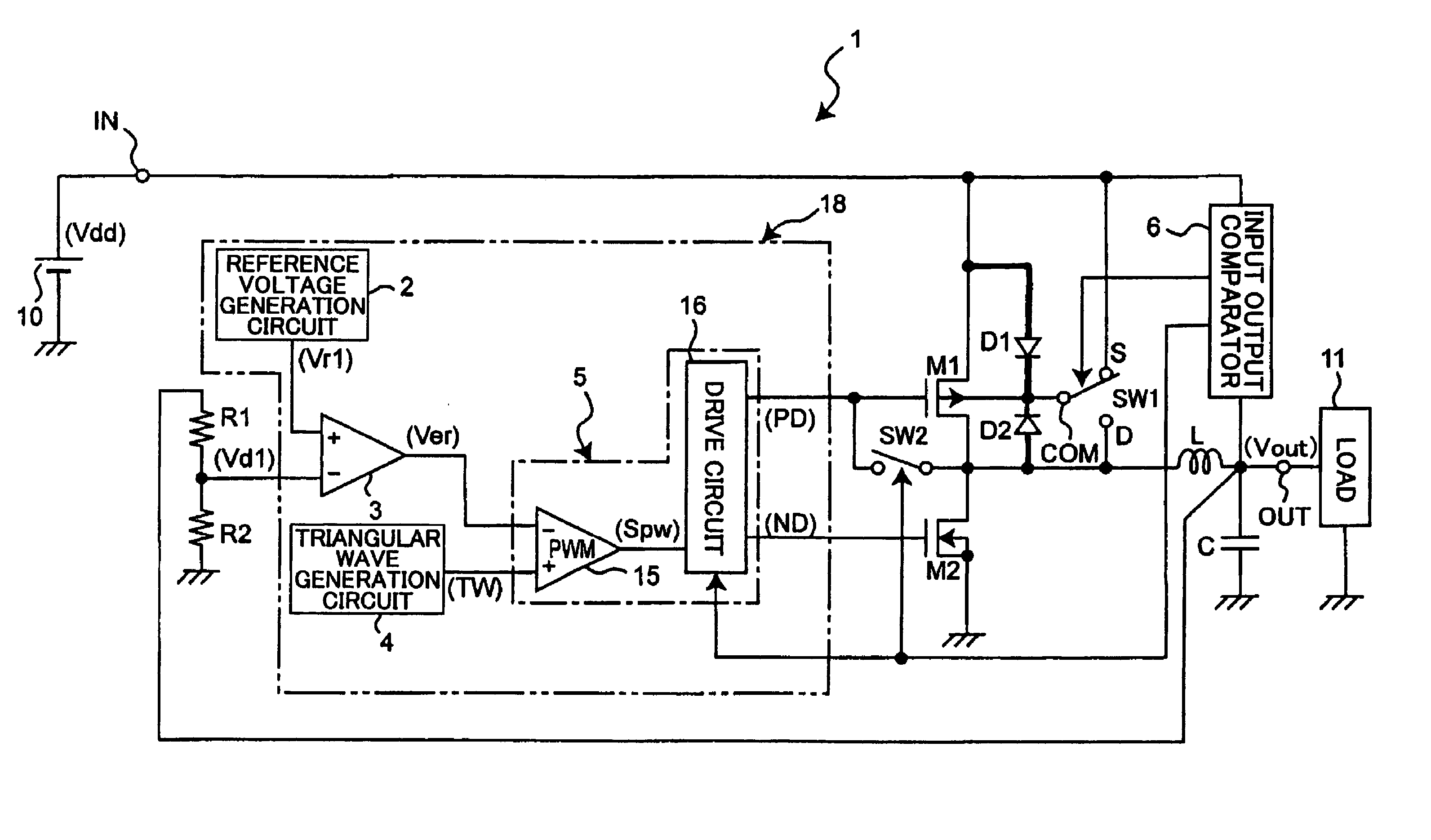
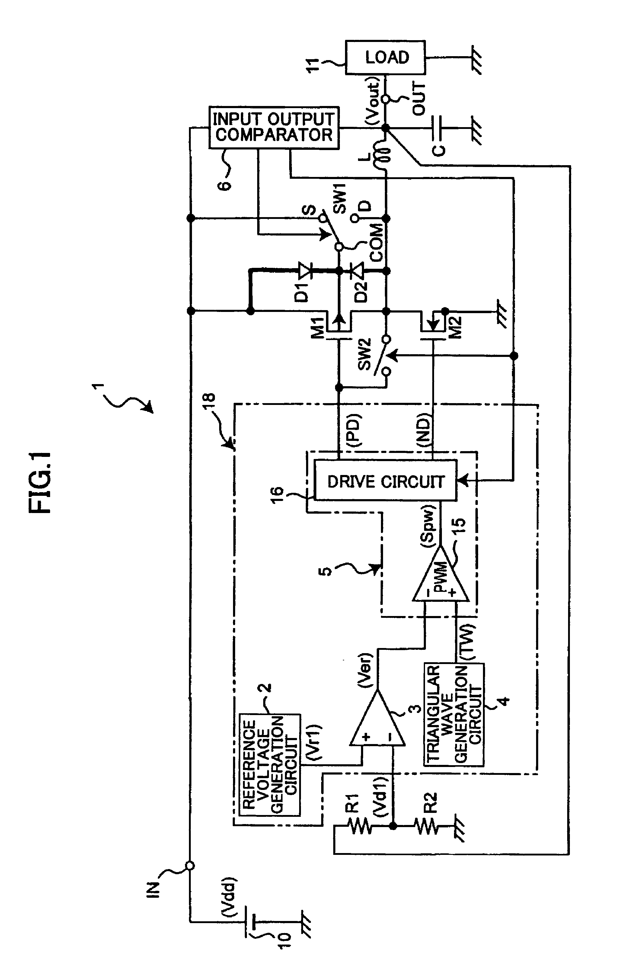
[0054]FIG. 1 is a circuit diagram exemplifying a switching regulator according to an embodiment of the present invention.

[0055]As illustrated in FIG. 1, in a step-down switching regulator 1, a DC (direct current) power supply 10 is connected between an input terminal IN and ground, and the DC power supply 10 supplies an input voltage Vdd to the input terminal IN. The step-down switching regulator 1 converts the input voltage Vdd to a predetermined voltage and outputs the predetermined voltage from an output terminal OUT. A load 11 is connected between the output terminal OUT and ground.

[0056]The switching regulator 1 includes a switching transistor M1, which is a PMOS transistor, for controlling outputting of the input voltage Vdd supplied to the input terminal IN, a synchronization rectification transistor M2, which is an NMOS transistor, an inductor L and a condens...


PUM


Abstract

A switching regulator is disclosed that is able to prevent reverse direction current flow without using a dedicated diode even when a PMOS transistor is used as a switching transistor of a step-down switching regulator. A selection circuit is provided to control connection of the substrate gate of the switching transistor, and a control circuit controls the selection circuit to connect the substrate gate to the drain of the switching transistor when the voltage on an input terminal of the switching regulator is less than or equal to the voltage on the output terminal of the switching regulator, and connect the substrate gate to the source of the switching transistor when the voltage on the input terminal is greater than the voltage on the output terminal.

Description

TECHNICAL FIELD[0001]The present invention relates to a switching regulator, a power supply circuit using the switching regulator, and a secondary cell charging circuit including the switching regulator, and particularly, to a switching regulator to an output terminal of which a voltage is applied and which has a circuit capable of preventing reverse direction flow of an electric current to an input terminal from a power supply connected to the output terminal.BACKGROUND ART[0002]In the related art, PMOS (P-channel metal oxide semiconductor) transistors are widely used as switching elements of step-down switching regulators, and voltage control elements of linear regulators. In addition, power supply circuits using PMOS transistors as control elements are employed in secondary cell charging circuits, in parallel running power supply circuits in which output terminals of plural power supplies are connected to each other to supply electric power to loads, and in backup power supply ci...

Claims


Application Information

Patent Timeline
Patent Type & Authority Patents(United States)
IPC IPC(8): G05F1/56
CPCH01M10/44H02M3/156H01M10/48Y02E60/10H02M3/155
Inventor NISHIDA, JUNJI
Owner RICOH KK
Learn More