Method and apparatus for propulsion and power generation using spinning electrodynamic tethers

a technology of electrodynamic tethers and propulsion systems, applied in the direction of transportation and packaging, aircrafts, spacecraft, etc., can solve the problems of virtually impossible to operate electrodynamic tether systems anywhere near the boundary of “static stability

Inactive Publication Date: 2005-09-13
STAR TECH & RES
View PDF20 Cites 61 Cited by
  • Summary
  • Abstract
  • Description
  • Claims
  • Application Information

AI Technical Summary

Benefits of technology

[0061]It is a primary advantage of the present invention that spinning electrodynamic tether systems can perform much better than conventional non-spinning systems and their design can be much more economical and efficient.

Problems solved by technology

This patent does not disclose design, operational, and performance advantages and methods of use of spinning (fast-rotating) electrodynamic tethers.
It does not disclose electrodynamics or use of magnetic fields.
They pointed out that it would be virtually impossible to operate electrodynamic tether systems anywhere close to the boundaries of “static stability” because of a very strong, uncontrollable or hardly controllable dynamic instability in these regions.
This was attributed to the dynamic stability constraints.
Rotation, however, has been considered detrimental to the performance of conventional electrodynamic tether systems.
. . electrodynamic forces can become quite significant, and without control over the tether dynamics, the instabilities can result in the tether ‘flipping over’ or even beginning to rotate, with a resultant loss of deorbit efficiency and control over the tether system.” As claimed in the '544 Patent cited earlier, the optimal performance of an electrodynamic tether for deorbiting satellites is achieved in a non-spinning mode, with the tether hanging at a certain fixed angle relative to the local vertical.

Method used


Image

  • Method and apparatus for propulsion and power generation using spinning electrodynamic tethers
  • Method and apparatus for propulsion and power generation using spinning electrodynamic tethers
  • Method and apparatus for propulsion and power generation using spinning electrodynamic tethers

Examples


Embodiment Construction

[0069]In the following detailed description of the invention, reference is made to the accompanying drawings, which form a part hereof, and in which is shown by way of illustration specific embodiments in which the invention may be practiced. It is to be understood that other embodiments may be utilized and structural or logical changes may be made without departing from the scope of the present invention. The following detailed description, therefore, is not to be taken in a limiting sense, and the scope of the present invention is defined by the appended claims.

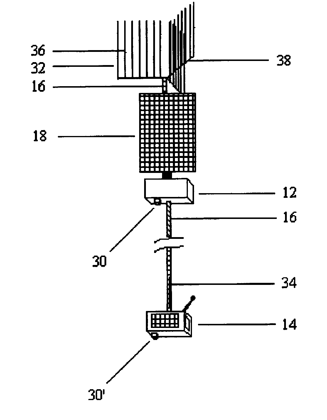
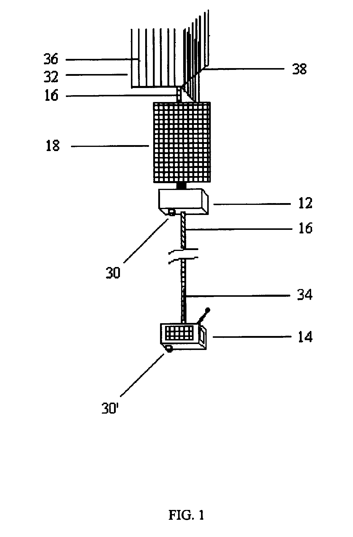
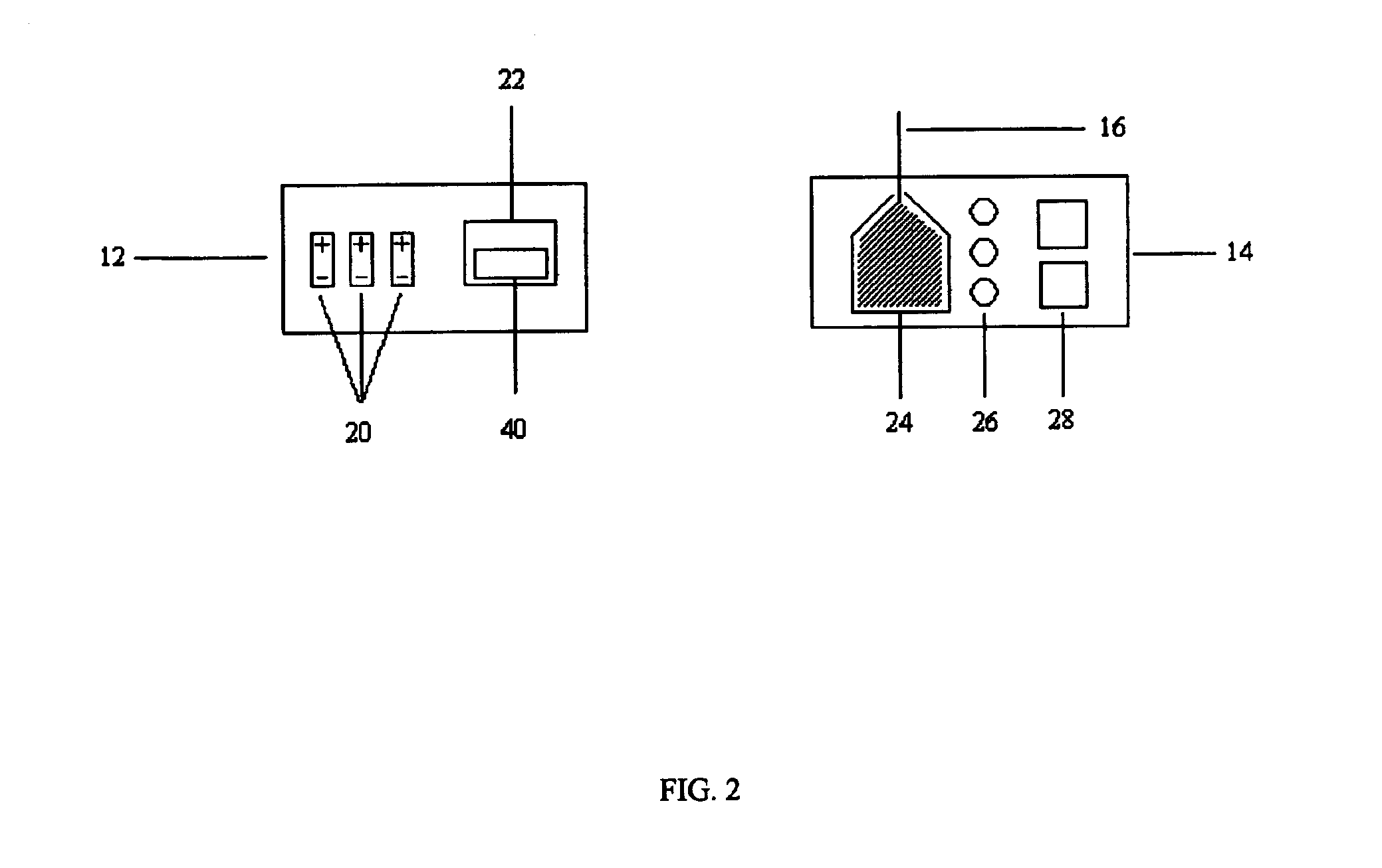
[0070]The present invention relates to spinning (fast-rotating) electrodynamic tethers. Electrodynamic tethers, also known as conducting tethers, are fully are partially made of conducting materials, or may use conductive coatings. Electric current can flow through such a tether (or some segments of the tether) closing the circuit through ambient plasma in a magnetic field. The conductivity provides for energy transfer (e.g...


PUM


Abstract

The present invention improves the orbital maneuvering and power generation capabilities of a system of a satellite(s) connected with a conducting tether(s) by spinning the system about its mass center at an angular rate which is relatively high compared to the average orbital rate. An improvement in tether performance is achieved because at many times during rotation the tether is positioned at much better angles with the magnetic field and significantly higher currents are driven through the tether without destabilizing the system. The current can flow either in the direction of the EMF induced in the tether, or in the reverse direction, depending on the tether orientation with respect to the magnetic field and the mission goals. The reverse current is driven by the onboard power sources. Spinning electrodynamic tether systems can also be lighter and simpler in design and more flexible in operation.

Description

CROSS-REFERENCE TO RELATED APPLICATIONS[0001]This application claims the benefit of the filing of U.S. Provisional Patent Application Ser. No. 60 / 274,072, entitled “Method and Apparatus for Propulsion and Power Generation Using Spinning Electrodynamic Tethers,” filed on Mar. 7, 2001, and the specification thereof is incorporated herein by reference.GOVERNMENT INTEREST[0002]This invention was made with Government support under Government Contract No. F29601-00-C-0034 awarded by the United States Air Force. The Government has certain rights in the invention.BACKGROUND OF THE INVENTION[0003]1. Field of the Invention (Technical Field)[0004]The present invention relates to orbital propulsion and power generation systems, and, more particularly, to a method and apparatus of using a spinning (fast-rotating) conducting tether to produce an electrodynamic propulsion force to change the orbit of a satellite through the interaction between the electric current in the tether and the external ma...

Claims


Application Information

Patent Timeline
Patent Type & Authority Patents(United States)
IPC IPC(8): B64G1/24B64G1/32
CPCB64G1/648B64G1/40B64G1/646B64G1/425B64G1/428B64G1/44
Inventor LEVIN, EUGENE M.CARROLL, JOSEPH A.
Owner STAR TECH & RES
Why Eureka
Try Eureka