Optical sheet lamination

a technology of optical sheets and lamination, applied in the direction of prisms, mountings, instruments, etc., can solve the problems of a particular surface light source, the primary function of a prism sheet for improving brightness, and the disassembly of pixels in images

Inactive Publication Date: 2003-05-29
DAI NIPPON PRINTING CO LTD
View PDF4 Cites 20 Cited by
  • Summary
  • Abstract
  • Description
  • Claims
  • Application Information

AI Technical Summary

Benefits of technology

[0044] At least one lens sheet which has one surface of a light-transmissive base material in said surface light source on which at least one of a group of plural unit prisms and a group of plural unit lenses arranged, and the other surface being made flat and smooth without raggedness by being covered with a coating layer formed out of a light-transmissive material is put between said optical sheet and said light outputting surface.
[0059] At least one lens sheet which has one surface of a light-transmissive base material in said light-transmissive display apparatus on which at least one of a group of plural unit prisms and a group of plural unit lenses is arranged and the other surface being made flat and smooth without raggedness by being covered with a coating layer of a light-transmissive material may be put between said optical sheet and said light outputting surface in said surface light source device.
[0068] According to the present invention, since many fine knoll-shaped projections of 1 to 10 .mu.m in height are provided on a coating layer covering the reverse surface opposite to the lens surface of a lens sheet, a gap of 1 to 10 .mu.m is formed between said reverse surface and the flat and smooth surface of a light guide plate, a light diffusing plate, another lens sheet or the like disposed adjacently to said reverse surface, and thereby the distance between said reverse surface and the flat and smooth surface of a light guide plate or the like is kept so that no interference is generated between an advancing light and a reflected light and thus generation of interference fringes or Newton's rings can be prevented.
[0070] According to the present invention, since light-transmissive beads are distributed unevenly more at the vicinity of the surface of a coating layer in case of providing many fine knoll-shaped projections of 1 to 10 .mu.m in height by distributing the light-transmissive beads in the coating layer covering the reverse surface opposite to the prism surface of a prism sheet, the invention is economical and efficient thanks to doing with a small amount of beads to be used, and can suppress a phenomenon of deteriorating the primary function of a prism sheet of improving the brightness of a display screen by collecting light in the direction perpendicular to the light outputting surface which phenomenon comes into question in case of forming a light diffusing layer on the reverse surface opposite to its prism surface of a prism sheet. Since the coating layer is hardened and formed in a state where an ink containing light-transmissive beads smaller in specific gravity than the light-transmissive resin is applied to the light-transmissive base material and the light-transmissive beads have come up to the surface of the ink thanks to the difference in specific gravity between them, it is possible to easily and surely distribute the light-transmissive beads unevenly more in the vicinity of the surface of the coating layer.
[0071] According to the present invention, since spherical beads are contained in a coating layer which covers the reverse surface opposite to the lens surface or the prism surface of an optical sheet or the reverse surface of an optical sheet having a light diffusing layer on its obverse surface, a small gap is formed between said reverse surface and the flat and smooth surface of a light guide plate, a light diffusing plate, another prism sheet or the like disposed adjacently to said reverse surface, and a light diffusing effect by the spherical beads prevents interference between an advancing light and a reflected light due to a distance between said reverse surface and the flat and smooth surface of a light guide plate or the like and prevents generation of interference fringes or Newton's rings. And since the spherical beads contained in the coating layer are 1 .mu.m or less in half bandwidth of the distribution of particle diameters, the projections from the reverse surface of an optical sheet vary a little in height and are uniformly in contact with another optical sheet such as a prism sheet or the like, and therefore a trouble is prevented that a prism or the like of another optical sheet is broken by a concentrated load caused by a greatly projected spherical bead.

Problems solved by technology

In an optical sheet as described above, a pattern where bright and dark parts are alternately repeated by light from a surface light source is observed in case of combination of a light guide means, a diffusing sheet, another optical sheet and the like, and a problem that an image composed of pixels is disarranged has been caused by this in case that such an optical sheet is used in a liquid crystal display apparatus, for example.
On the other hand, a method of forming minute rugged parts satisfying a particular condition on the flat and smooth surface of a prism sheet is also conceivable as disclosed in said Tokkaihei No. 7-151909, but in this case, there is a problem that the primary function of a prism sheet for improving the brightness by collecting light from a surface light source in a particular direction, for example, in the normal direction to the light outputting surface is deteriorated.
Such a prism sheet having a light diffusing sheet laminated on it has a problem that a prism (or lens) part touching the light diffusing sheet is damaged by a rugged part on the surface of the light diffusing sheet and this flaw deteriorates a uniform and flat light-emitting state as a whole.
On the other hand, although a method of forming the prism sheet side of a light diffusing sheet into a flat and smooth surface in the same way as the light inputting surface of said prism sheet is also conceivable, such a method as this has not come to be in practical use since there is a problem that interference fringes or moire patterns are generated between the flat and smooth surface of said light diffusing sheet and the flat and smooth surface of a light guide plate or the flat and smooth surface of a prism sheet.
Hereupon, the reason why the projections of said spherical beads 20 are made 1 .mu.m or more in height from the surface of the coating layer 18 is that a height of less than 1 .mu.m causes a problem that said gap 24 being close to the wavelength of a surface light-source light (visible light) makes color appear, a problem that it becomes difficult to mass-produce light-transmissive beads (acryl beads for example) as a material for the spherical beads 20, and a problem that such fine beads are difficult to be dispersed in a binder (described later) forming the coating layer 18.

Method used


Image

  • Optical sheet lamination
  • Optical sheet lamination
  • Optical sheet lamination

Examples


Embodiment Construction

[0214] As a result, interference fringes have been observed only in the comparison example 1 in Table 1.

[0215] When a single optical sheet of embodiment 1 in Table 1 and an optical sheet having the obverse surface having unit prisms each of which is an isosceles-triangular prism whose vertical angle is 90.degree. and the reverse surface which is flat and smooth are assembled, as shown in FIG. 16, in said surface light source device, an exemplary embodiment is obtained.

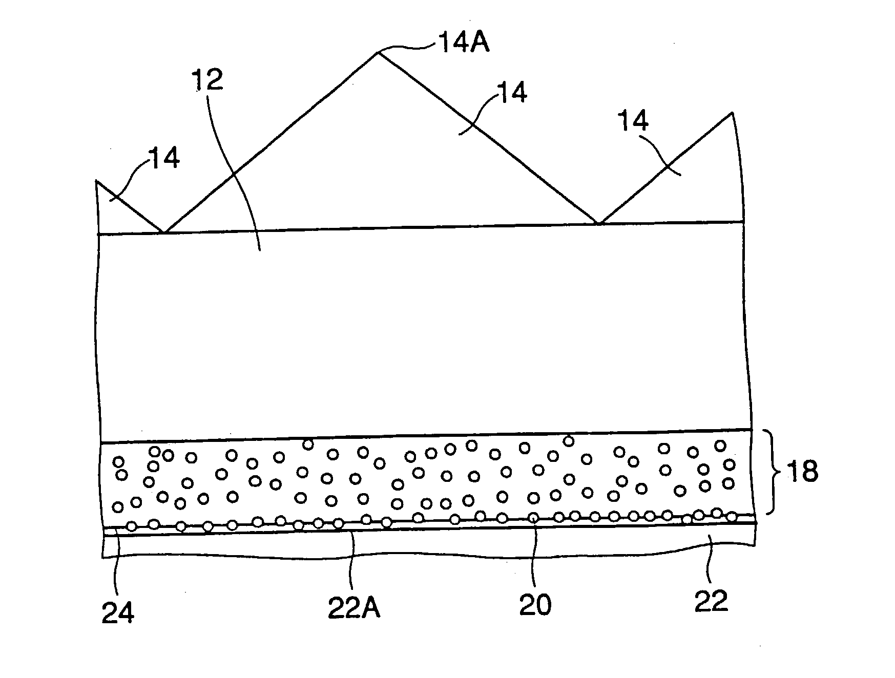
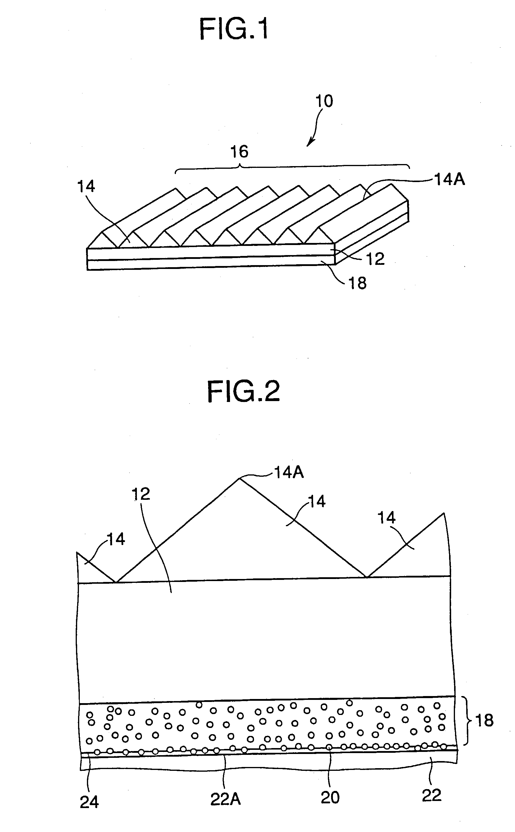
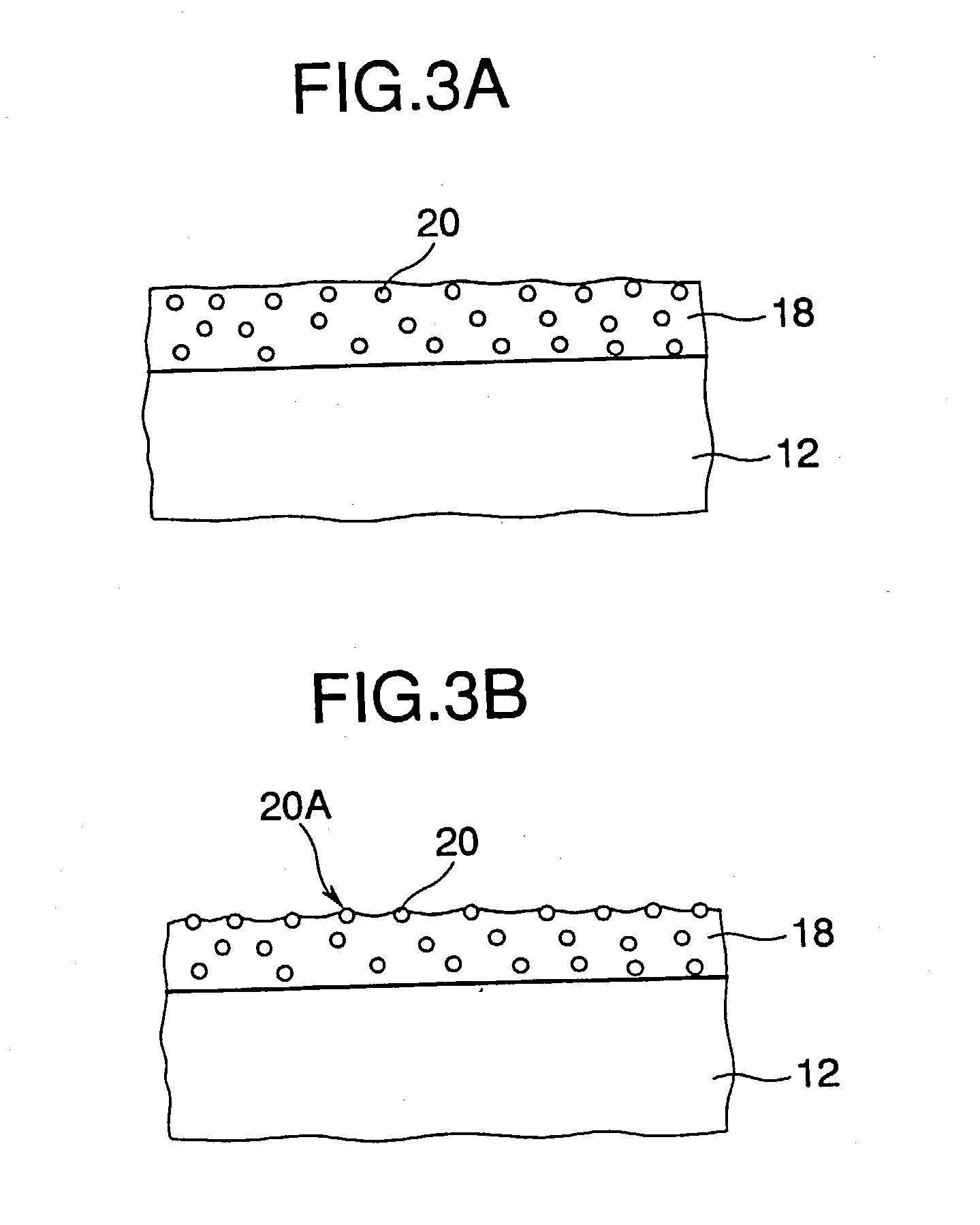
[0216] As a result of experiments in which an optical sheet coated with spherical beads 20 having a particle diameter distribution according to the present invention and an optical sheet coated with spherical beads 20A having another particle diameter distribution more greatly varying in particle diameter are respectively dragged, for example, in a state where the spherical beads side of each of them is in contact with a prism surface and a 10-g weight is put on it, the greater the particle diameter distribution is in ...


PUM

PropertyMeasurementUnit
heightaaaaaaaaaa
particle diameteraaaaaaaaaa
particle diametersaaaaaaaaaa

Abstract

In an optical sheet 10 having a prism surface 16 formed by providing unit prisms 14 on the upper surface of a transparent base material 12, a coating layer 18 is provided on the reverse surface of the transparent base material opposite to the prism surface 16, spherical beads 20 are arranged projecting from the surface of the coating layer 18 by 1 to 10 mum in height, and the coating layer 18 is brought into contact with the flat and smooth surface 22A of the light-transmissive material 22 through the spherical beads 20 which are put between them. The spherical beads are 1 mum or less in half bandwidth of the distribution of particle diameters and are made uniform in height projecting from the coating layer 18.

Description

[0001] 1. Field of the Invention[0002] The present invention relates to an optical sheet and an optical sheet lamination ("lamination" includes stacking or putting on in not contact with another) composed of a prism sheet, a lens sheet and / or an optical diffusing sheet suitable for use in a back light surface light source used in illuminating from the back a light-transmissive type display panel of a light-transmissive type liquid crystal display apparatus, an advertising board or the like, and a surface light source device and a light-transmissive type display apparatus using the same optical sheet or optical sheet lamination.[0003] 2. Prior Art[0004] In a liquid crystal display apparatus in recent years, according to necessity of reducing of its power consumption and making it thin and light in shape and weight, a surface light source for illuminating the liquid crystal display apparatus from the back has been naturally required also to be made thin and light in shape and weight a...

Claims


Application Information

Patent Timeline
Patent Type & Authority Applications(United States)
IPC IPC(8): F21V8/00G02B5/02G02B5/04
CPCG02B5/021G02F2001/133607G02B5/0226G02B5/0231G02B5/0242G02B5/0278G02B5/045G02B6/0031G02B6/0038G02B6/0041G02B6/0043G02B6/0046G02B6/005G02B6/0051G02B6/0053G02B6/0055G02B6/0071G02F1/133606G02B5/0215G02F1/133607
Inventor KASHIMA, KEIJIARAKAWA, FUMIHIRO
Owner DAI NIPPON PRINTING CO LTD
Why Eureka
Try Eureka