Outer rotor type permanent magnetism synchronization gear wheel free traction machine

A technology of gear traction machine and permanent magnet synchronization, which is applied in the field of traction machine, can solve the problems of out-of-tolerance runout of the groove surface of the traction wheel, non-concentricity of the rotor and the shaft, and runout of the outer surface of the rotor, so as to achieve small surface runout, The effect of low machine height and high rotor concentricity

Active Publication Date: 2011-05-04
KINETEK DE SHENG SHUNDE MOTOR CO LTD
View PDF1 Cites 0 Cited by
  • Summary
  • Abstract
  • Description
  • Claims
  • Application Information

AI Technical Summary

Problems solved by technology

On the one hand, in order to control the cantilever from being too long, on the other hand, to save the material of the traction sheave and control the length of the whole machine, the matching section between the traction sheave and the shaft is relatively short. Therefore, the following problems often occur in production: 1. The runout of the pulley groove surface is out of tolerance; 2. The coaxiality error of the traction sheave will be transmitted to the rotor, resulting in serious runout of the outer surface of the rotor; 3. Due to the large cumulative error, the rotor and the shaft often have misalignment
In view of the above problems, Chinese patent 200610050802.9 (small permanent magnet synchronous gearless traction machine) proposes a structure in which the traction wheel and the shaft are cast as one. During processing, the traction wheel and the shaft are processed at the same time, which can overcome the existing external rotor. The above-mentioned problems exist in the permanent magnet synchronous gearless traction machine, but because the traction sheave is a wearable part, it needs to be replaced after wear, and when the structure is replaced, it needs to be replaced together with the rotating shaft, and when replacing, the rotor must be pulled out completely , very inconvenient to operate

Method used


Image

  • Outer rotor type permanent magnetism synchronization gear wheel free traction machine
  • Outer rotor type permanent magnetism synchronization gear wheel free traction machine
  • Outer rotor type permanent magnetism synchronization gear wheel free traction machine

Examples


Embodiment Construction

[0012] The present invention will be further described below in conjunction with accompanying drawing and embodiment:

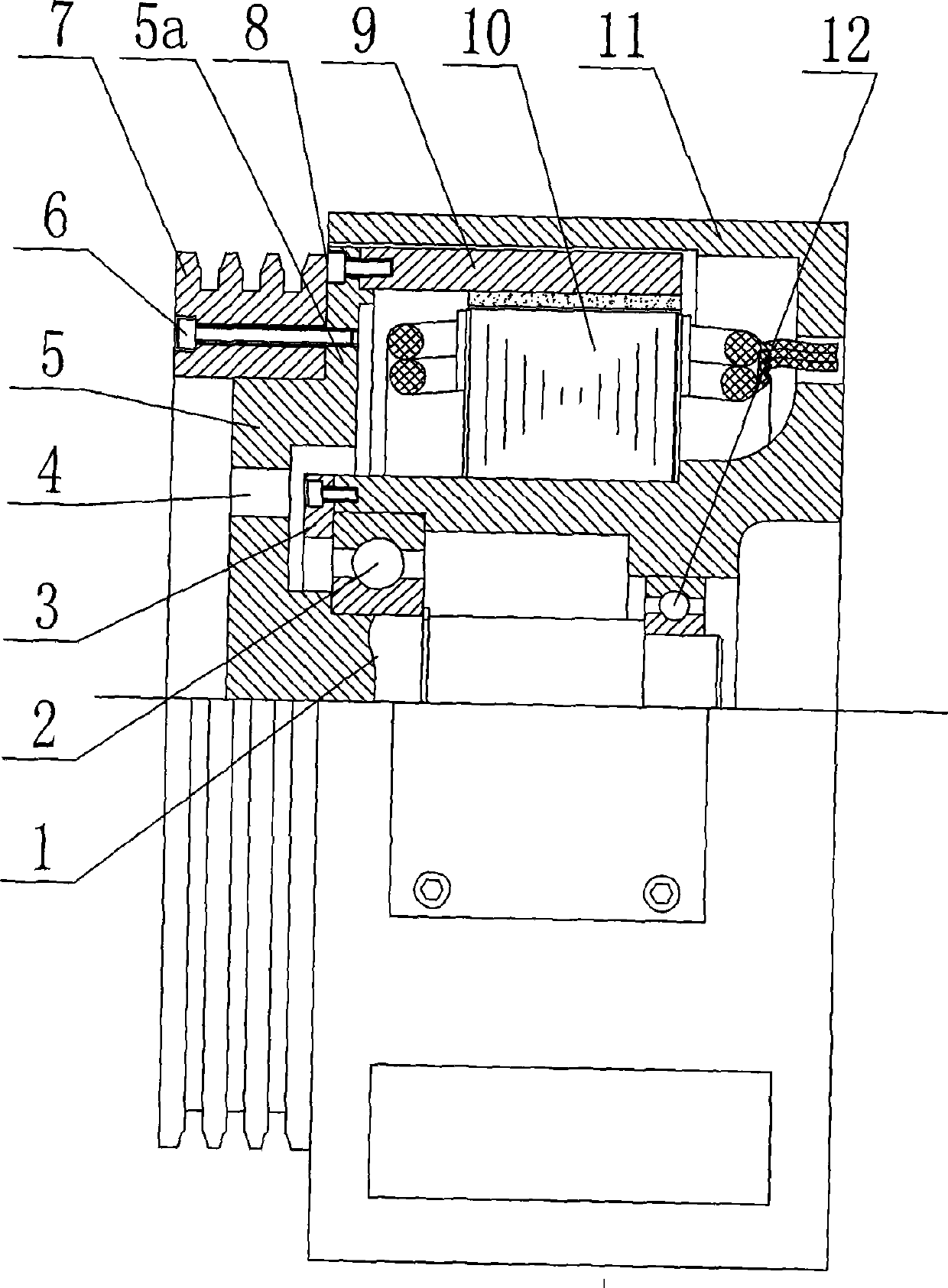
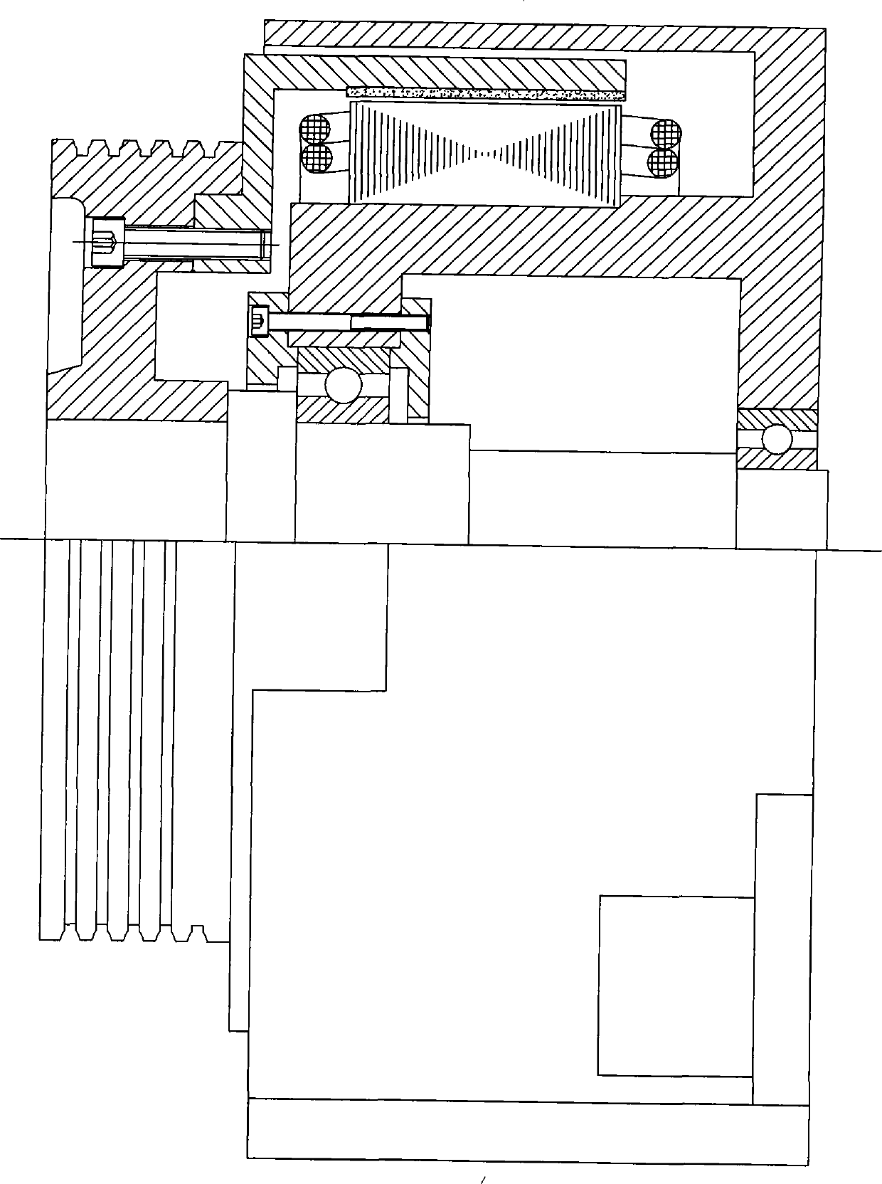
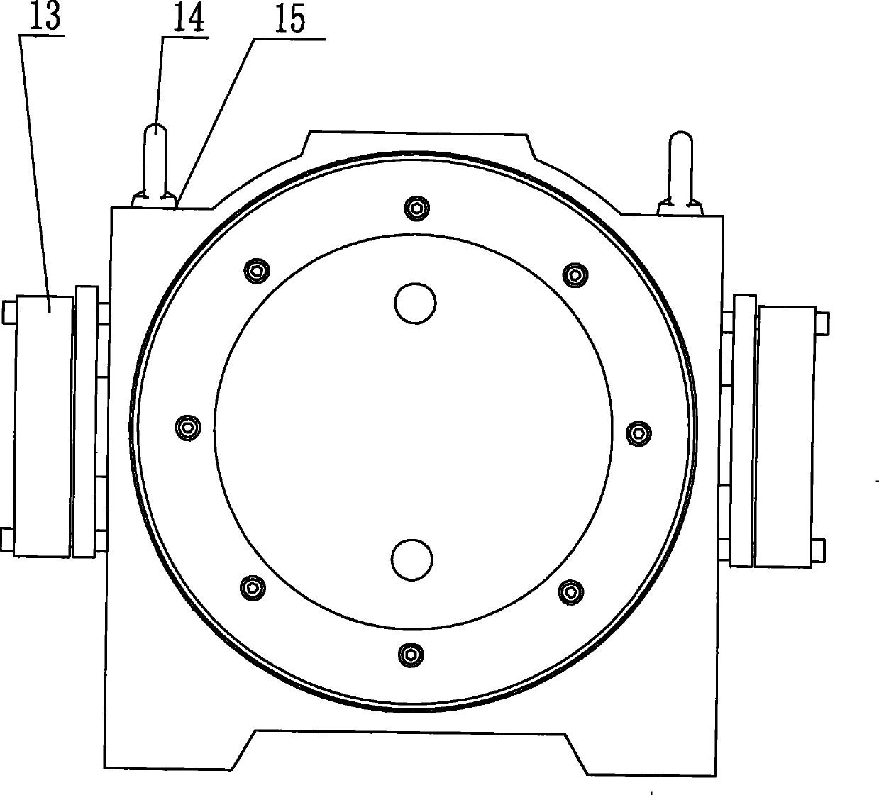
[0013] The structure of an outer rotor type permanent magnet synchronous gearless traction machine of the present invention is as follows: figure 2 As shown, its structure is mainly composed of shaft 1, front bearing 2, spoke 5, traction wheel 7, outer rotor 9, inner stator 10, frame 11, rear bearing 12, and brake 13. The inner stator 10 is fastened and installed on the machine. The outer rotor 9 is located outside the stator 10 and fixed on the right end of the spoke 5 by the rotor screw 8 on the support sleeve protruding from the inside of the seat 11, and the traction wheel 7 is fixed on the left end of the spoke 5, and the shaft 1 and the spoke 5 are integrally cast The structure is supported by the front bearing 2 and the rear bearing 12 installed in the frame. Since the shaft 1 and the spoke 5 are integrally structured, they are processed together dur...


PUM


Abstract

The invention provides an external rotor permanent magnetic synchronous no-gear tractor, comprising a frame, an internal stator which is arranged on the frame, an external rotor which is arranged at the external side of the internal stator, a rotation shaft which is arranged on the frame by a bearing, and a traction wheel which is fixed on the rotation shaft and is fixedly connected with the external rotor; the external rotor permanent magnetic synchronous no-gear tractor is characterized in that the front end of the rotation shaft is provided with a spoke; the spoke and the shaft are a structure integrally cast; the traction wheel is fixed on the spoke. Compared with the prior art, the external rotor permanent magnetic synchronous no-gear tractor has the advantages of small jumping of surface of the traction wheel trough, high concentricity of rotor, convenient replacement of traction wheel, compact structure of whole machine, low height of whole machine, being used in no-machine rooms.

Description

technical field [0001] The invention relates to a traction machine, in particular to a permanent magnet synchronous gearless traction machine for elevators. Background technique [0002] The structure of the existing external rotor permanent magnet synchronous gearless traction machine is as follows: figure 1 As shown, the traction sheave is installed on the front end of the shaft, and the rotor is installed on the inner end face of the traction sheave. On the one hand, in order to control the cantilever from being too long, on the other hand, to save the material of the traction sheave and control the length of the whole machine, the matching section between the traction sheave and the shaft is relatively short. Therefore, the following problems often occur in production: 1. The runout of the pulley groove surface is out of tolerance; 2. The coaxiality error of the traction sheave will be transmitted to the rotor, resulting in serious runout of the outer surface of the rot...

Claims


Application Information

Patent Timeline
Patent Type & Authority Patents(China)
IPC IPC(8): B66D1/02B66D1/12B66D5/06H02K7/14H02K21/22
Inventor 梁昌勇
Owner KINETEK DE SHENG SHUNDE MOTOR CO LTD
Why Eureka
Try Eureka