
Embroidery machine

An embroidery machine and presser foot technology, which is applied to embroidery machines, embroidery machine mechanisms, cloth pressing mechanisms, etc., and can solve problems such as noise and easy damage of the presser foot frame 6

Inactive Publication Date: 2008-09-10
SUSR PRECISION CO LTD
View PDF0 Cites 38 Cited by
  • Summary
  • Abstract
  • Description
  • Claims
  • Application Information

AI Technical Summary

Problems solved by technology

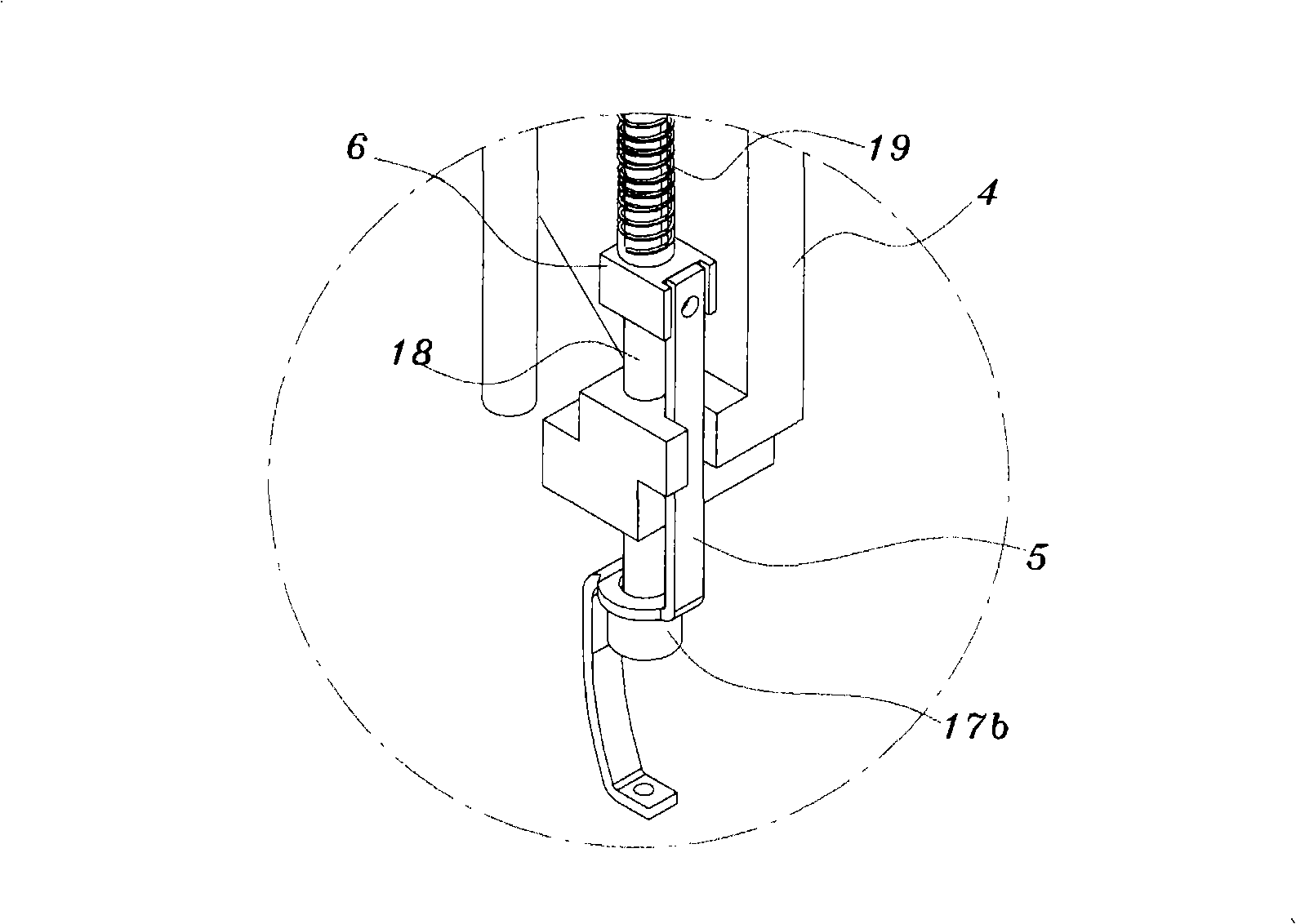
However, the contact between the needle bar support housing 4 and the presser foot frame 6 makes noise when touched
In addition, the presser foot frame 6 is often easily damaged due to frequent contact

Method used


Image

  • Embroidery machine
  • Embroidery machine
  • Embroidery machine

Examples


Embodiment Construction

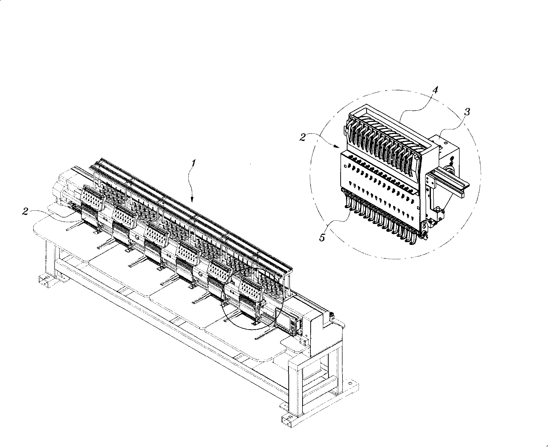
[0049] The embroidery machine of the present invention will be described more comprehensively below in conjunction with the accompanying drawings.

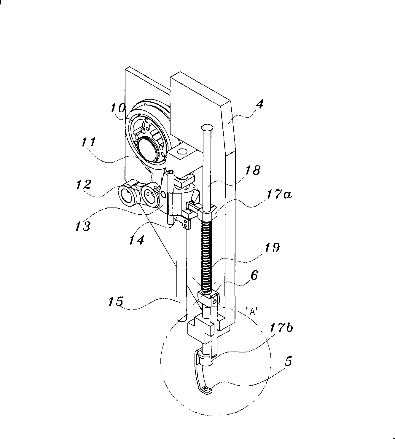
[0050] image 3 is a perspective view describing a sewing head having a presser foot driving structure according to an embodiment of the present invention, Figure 4A is a perspective view describing the presser foot driving structure of the present invention, Figure 4B is viewed from one direction Figure 4A Enlarged view of part "B" in, Figure 4C viewed from another direction Figure 4A Enlarged view of part "B" in, Figure 5 is a side view illustrating the presser foot driving structure of the present invention in an installed position.

[0051] refer to Figure 3 ~ Figure 5 , construct the embroidery machine of the present invention in such a way that each of the needle bar and the presser foot is driven by an independent drive mechanism.

[0052] in such as Figure 4A ~ Figure 5 In the shown presser foot drive mecha...


PUM


Abstract

An embroidery machine includes a sewing arm having an upper shaft for providing a driving force, a needle bar support case, which is assembled to a front portion of the sewing arm so as to be laterally movable, a needle bar provided in a needle bar support case, the needle bar having a needle at a lower end thereof and vertically carrying the needle using a rotation driving force of the upper shaft, and a presser foot, which is provided in the needle bar support case so as to be vertically movable, characterized in that each of the needle bar and the presser foot is operated by an individual drive mechanism. The presser foot is separately driven by its own drive source, independent of the drive source of the needle bar.

Description

technical field [0001] The present invention relates to an embroidery machine, and more particularly, to an embroidery machine in which a presser foot (cloth pressing member) can be driven independently by its own drive source independent from that of a needle bar. Background technique [0002] Generally, an embroidery machine is a two-axis positioning control machine, in which, while the needle bar moves up and down, the embroidery stitch frame for fixing the fabric moves horizontally along the X-axis and Y-axis directions. [0003] Since the embroidery machine performs embroidery work while conveying the embroidery stitch frame for fixing the fabric along the X-axis and Y-axis directions, the precise and constant speed movement of the embroidery frame is closely related to the quality of the embroidery pattern. [0004] Therefore, an embroidery machine driving source that transfers the needle bar in the vertical direction and transfers the embroidery stitch frame in the X-...

Claims


Application Information

Patent Timeline
Patent Type & Authority Applications(China)
IPC IPC(8): D05C9/20D05C11/06D05C13/00
CPCD05C9/20D05B19/12D05B29/12D05B29/02D05C3/02D05B55/14D05C11/06
Inventor 朴赞守
Owner SUSR PRECISION CO LTD
Learn More