
Generator air intake device

A technology of air intake device and generator, applied in the direction of machine/engine, mechanical equipment, etc., can solve problems such as engine damage and poor fuel atomization effect.

Inactive Publication Date: 2008-09-10
KYMCO
View PDF0 Cites 2 Cited by
  • Summary
  • Abstract
  • Description
  • Claims
  • Application Information

AI Technical Summary

Problems solved by technology

[0005] The problem to be solved by the present invention is to overcome the problem that the air intake of the air filter of the conventional generator is usually set towards the outside of the generator and the ground, and when the engine operates to generate negative pressure, it is easy to suck in excessive dust The absence of water causing engine damage, and the absence of poor fuel atomization from conventional air filter intake configurations

Method used


Image

  • Generator air intake device
  • Generator air intake device
  • Generator air intake device

Examples


Embodiment Construction

[0031] In order to make it easier for your examiner to understand the structure of the present invention and the effects that can be achieved, the accompanying drawings are described as follows:

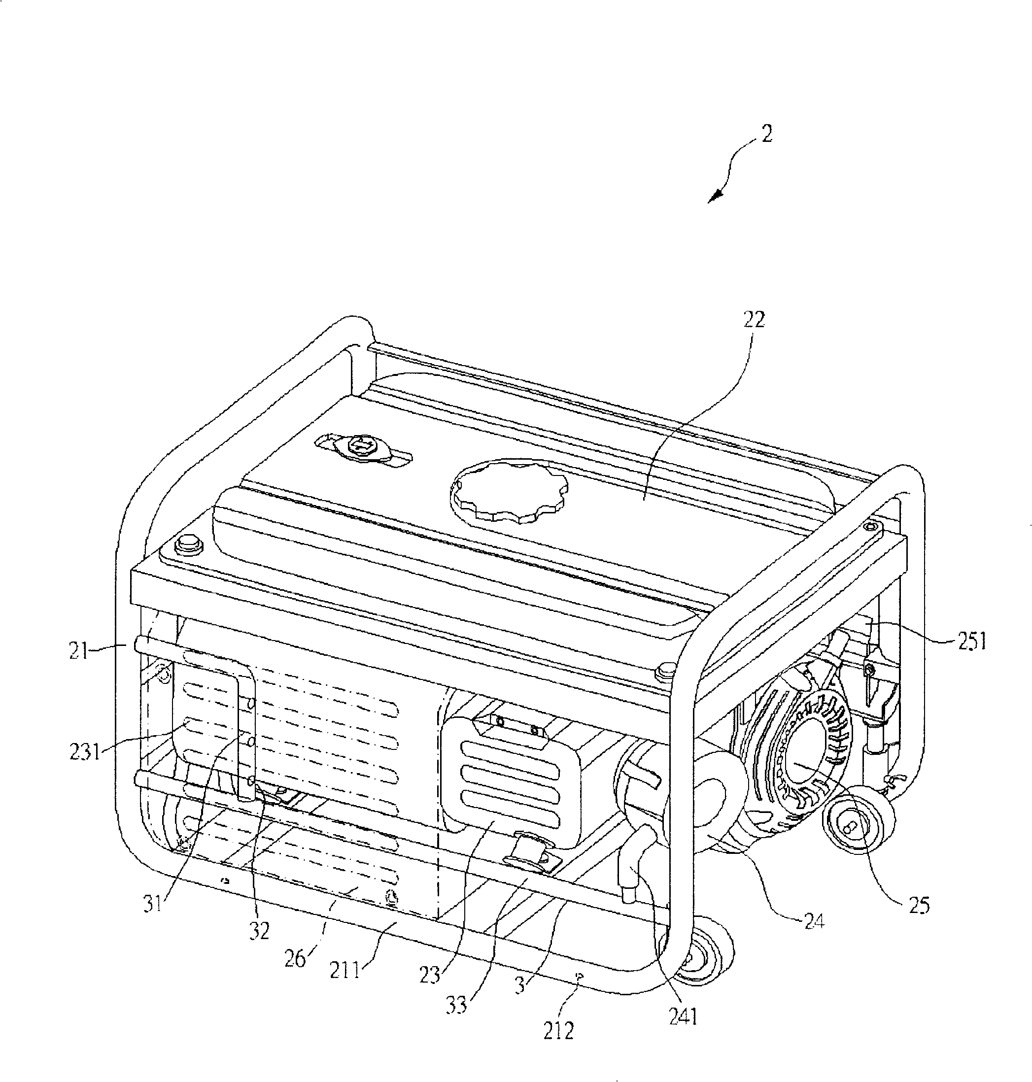
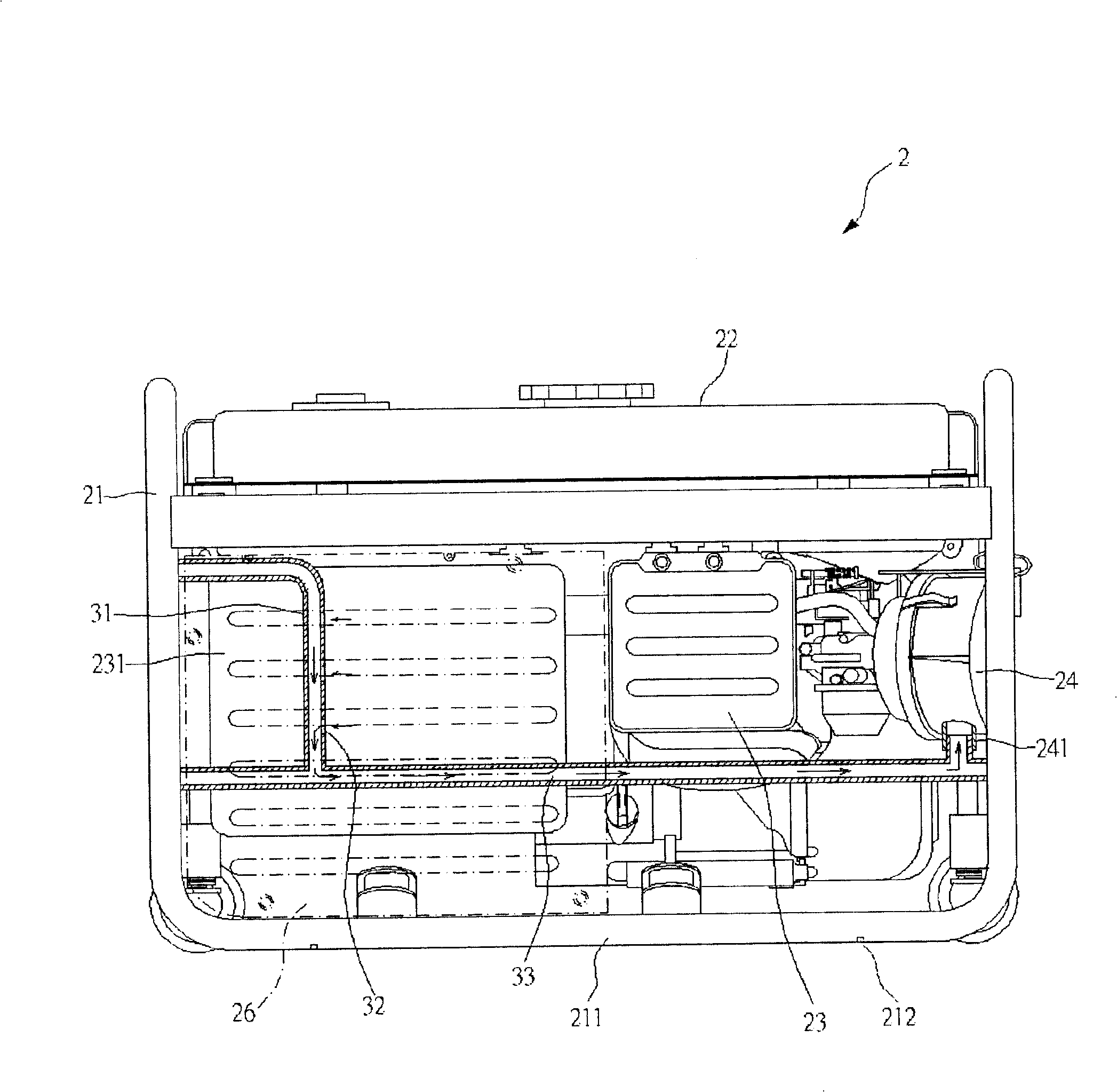
[0032] First, please refer to figure 2 As shown, the generator 2 of the present invention includes a fuel tank 22, an engine 23, an air filter 24, a cooling fan 25, a wind deflector 26, and a support frame 21 surrounding and supporting the above-mentioned components.

[0033] The support frame 21 is a hollow tube frame that can support all the components of the generator 2. The two sides of the support frame 21 are extended downward with an underframe 211. The bottom of the underframe 211 is provided with a plurality of drain holes 212. The drain The water hole 212 can be used for draining the accumulated water in the support frame 21 naturally, so as to prevent water from stagnating in the support frame 21 .

[0034] The fuel tank 22 is arranged above the support frame 21 , and th...


PUM


Abstract

The invention relates to an air inlet unit for a generator which is provided with a support; an oil box is arranged above the support, while an engine is arranged under the oil box; one side of the engine is connected with an air cleaner, while the other side of the engine is connected with an exhaust pipe; the air cleaner is extensibly provided with an inlet pipe; the support is provided with the air inlet unit which is provided with an air conduit, wherein, the air conduit is arranged towards the side of the exhaust pipe and is provided with an air intake, and a connecting pipe is extensibly arranged under the air conduit and is connected with the inlet pipe; therefore, the inlet end of the air cleaner can be positioned on the side of the exhaust pipe, when the engine is started, negative pressure is generated through the engine, hot air of the engine side and the exhaust pipe side can be introduced into the air cleaner through the air intake of the air conduit; therefore, the inlet pipe can be away from the ground to reduce dust and moisture which enter the air cleaner, and improve the atomization effect of fuel.

Description

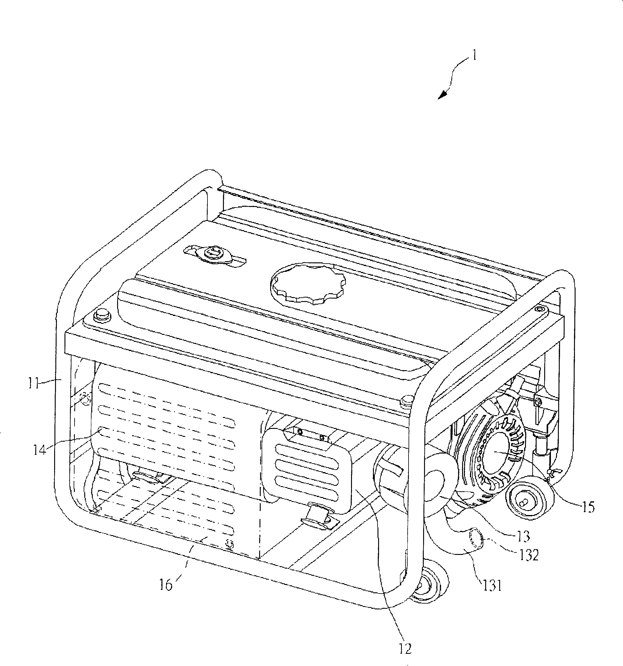
【Technical field】 [0001] The invention relates to an air intake device for a generator, especially a structure in which an air intake device is arranged on a support frame, and the air intake device is used to introduce hot air into an air filter. 【Background technique】 [0002] Press, the structure of known generator 1 is roughly as figure 1 As shown, the generator 1 has a support frame 11, an engine 12 is provided under the support frame 11, an air filter 13 is provided on one side of the engine 12, and an air intake pipe 131 is extended from the air filter 13. The intake pipe 131 can provide clean air for the combustion of the engine 12 when the engine 12 is running, and the other side of the engine 12 is connected with an exhaust pipe 14, and the exhaust pipe 14 can discharge the exhaust gas after the combustion of the engine 12. Air cleaner 13 is provided with cooling fan 15 besides, and this cooling fan 15 can introduce the cold air of outside, and blows to engine 12 ...

Claims


Application Information

Patent Timeline
Patent Type & Authority Applications(China)
IPC IPC(8): F02B63/04F02B67/10
Inventor 孙庆宏李三吉
Owner KYMCO
Learn More