Ellipse LED

A light-emitting diode and elliptical technology, which is applied in the field of elliptical light-emitting diodes, can solve problems such as the limitation of illuminance, and achieve the effect of expanding the irradiation range and improving light efficiency

Inactive Publication Date: 2008-09-10
PROLIGHT OPTO TECH
View PDF0 Cites 9 Cited by
  • Summary
  • Abstract
  • Description
  • Claims
  • Application Information

AI Technical Summary

Problems solved by technology

[0010] The object of the present invention is to provide an elliptical light-emitting diode, so as to achieve the purpose of expanding the irradiation range of the light source by means of the non-aligned light shape, so as to solve the problem of limited illuminance caused by the contrasting light shape of the existing light-emitting diodes

Method used


Image

  • Ellipse LED
  • Ellipse LED
  • Ellipse LED

Examples


Embodiment Construction

[0035] refer to Figure 6 , is a perspective view of the first embodiment of the present invention.

[0036] refer to Figure 7 , is a side view of the first embodiment.

[0037] refer to Figure 6 and Figure 7 The elliptical LED 100 of the first embodiment of the present invention has a power of at least 1 watt (W), and includes a base 110 , a chip body 120 , an LED lens 130 , and two metal terminals 140 .

[0038] The base 110 is an insulator.

[0039] The chip body 120 is a conductor (die), and is mounted on the middle position of the top surface of the base 110 .

[0040] The metal terminal 140 is disposed around the base 110 and is electrically connected to the chip main body 120 .

[0041] Figure 8 It is another side view of the first embodiment.

[0042] refer to Figure 6 , Figure 7 and Figure 8 , the LED lens 130 is covered on the chip main body 120 . The LED lens 130 has a transmissive portion 131 and a horizontal flange 132 disposed around the transm...


PUM


Abstract

The invention discloses an elliptical light emitting diode with the power of at least 1 watt, which comprises a chip body and a lens of the light emitting diode. The lens of the light emitting diode is covered and arranged on the chip body and provided with a transmission part. The transmission part is provided with a long shaft and a short shaft, wherein, the ratio of light forms scattered by the long shaft and the short shaft is more than or equal to 1.5-5.

Description

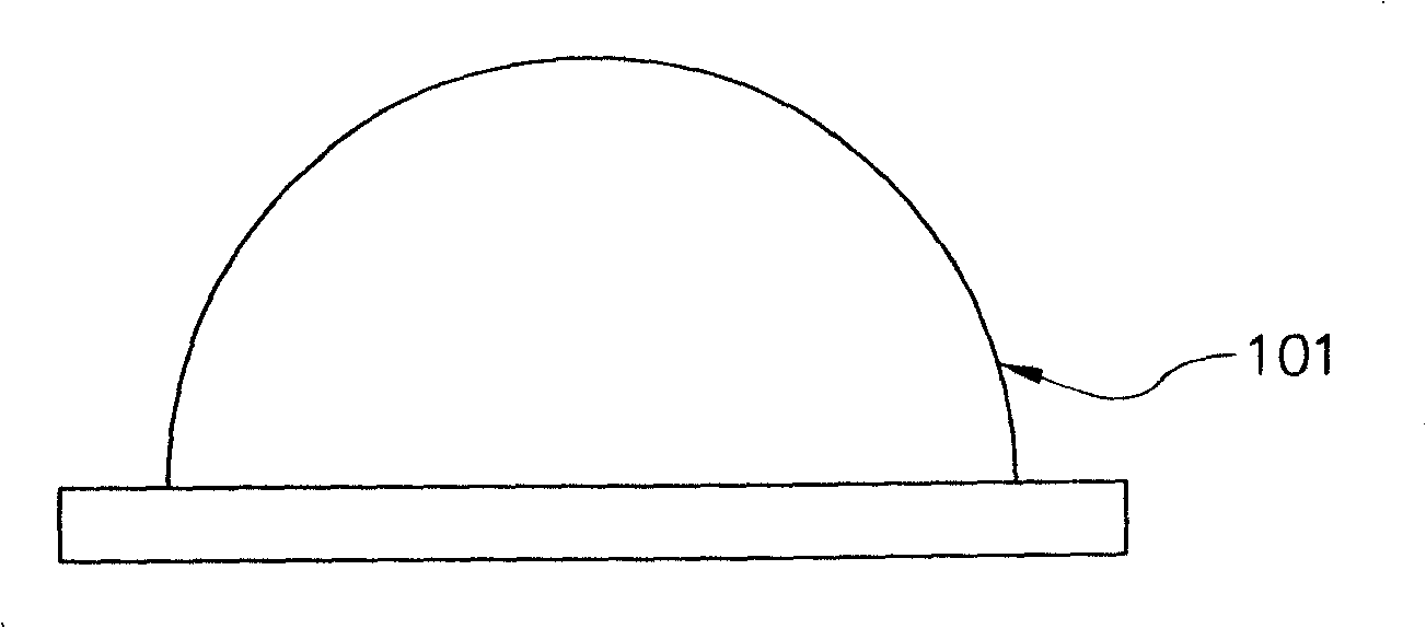
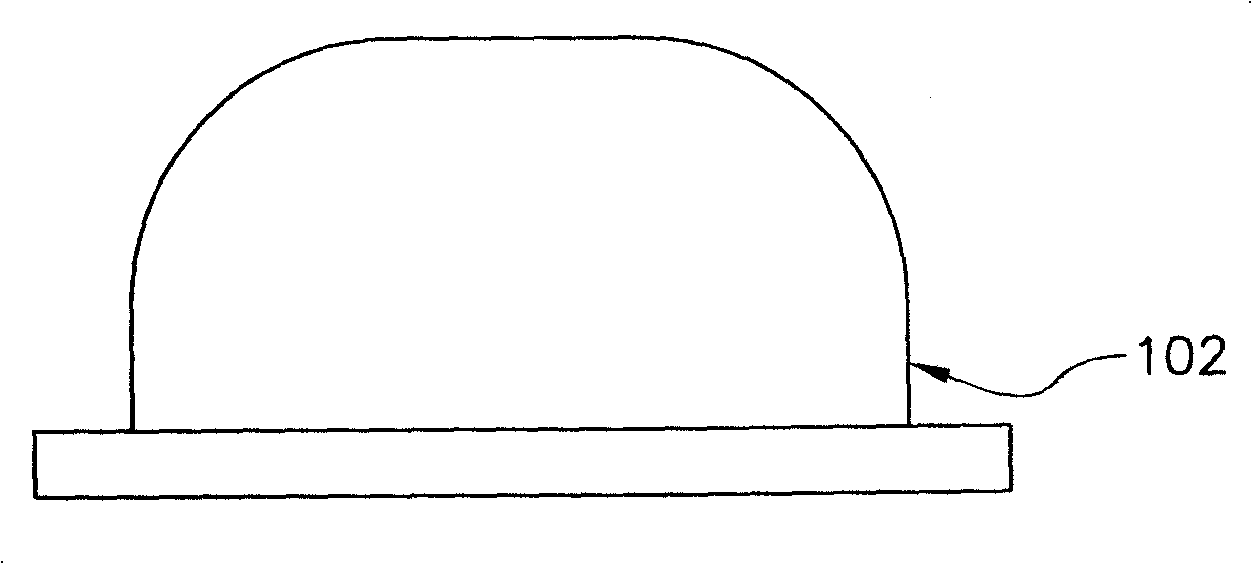
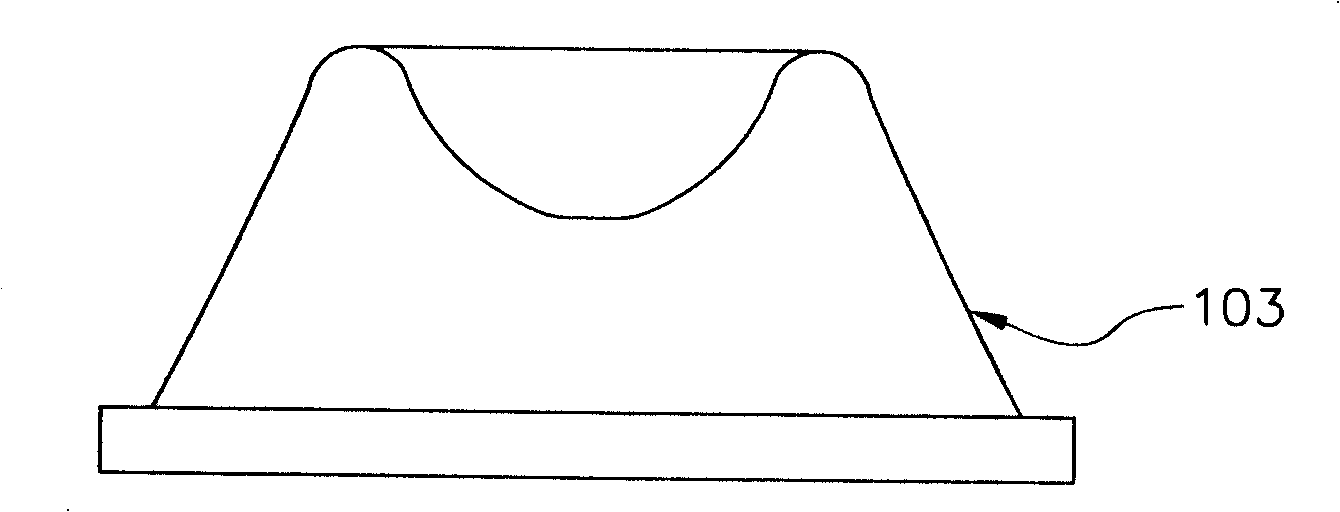
technical field [0001] The invention relates to a high-power light-emitting diode, in particular to an elliptical light-emitting diode capable of increasing illuminance. Background technique [0002] Existing light-emitting diodes (LEDs) use LED grains to generate light sources, and the LED lens (Lens) covering the periphery of the LED grains assists in scattering the light source outwards to achieve lighting effects. [0003] refer to figure 1 , is the first known hemispherical lens (Lens) 101 for light-emitting diodes, which is a blue reflector type (Lambertian Patten). [0004] refer to figure 2 , which is the second type of flat lens (Lens) 102 known in the art for light-emitting diodes. [0005] refer to image 3 , which is the third known airfoil lens (Lens) 103 for light-emitting diodes. [0006] refer to Figure 4 , which is the third type of side-scattering lens (Lens) 104 known in the art for light-emitting diodes. [0007] refer to Figure 5 , which is th...

Claims


Application Information

Patent Timeline
Patent Type & Authority Applications(China)
IPC IPC(8): H01L33/00G02B3/00H01L33/58
Inventor 邢陈震仑洪荣豪
Owner PROLIGHT OPTO TECH
Why Eureka
Try Eureka