

Electric conductor for vehicle
A vehicle and conductor technology, applied in conductors, insulated conductors, rigid tube cables, etc., can solve problems such as the increase in the number of protector parts
- Summary
- Abstract
- Description
- Claims
- Application Information
AI Technical Summary
Problems solved by technology
Method used
Image


Examples
no. 1 example
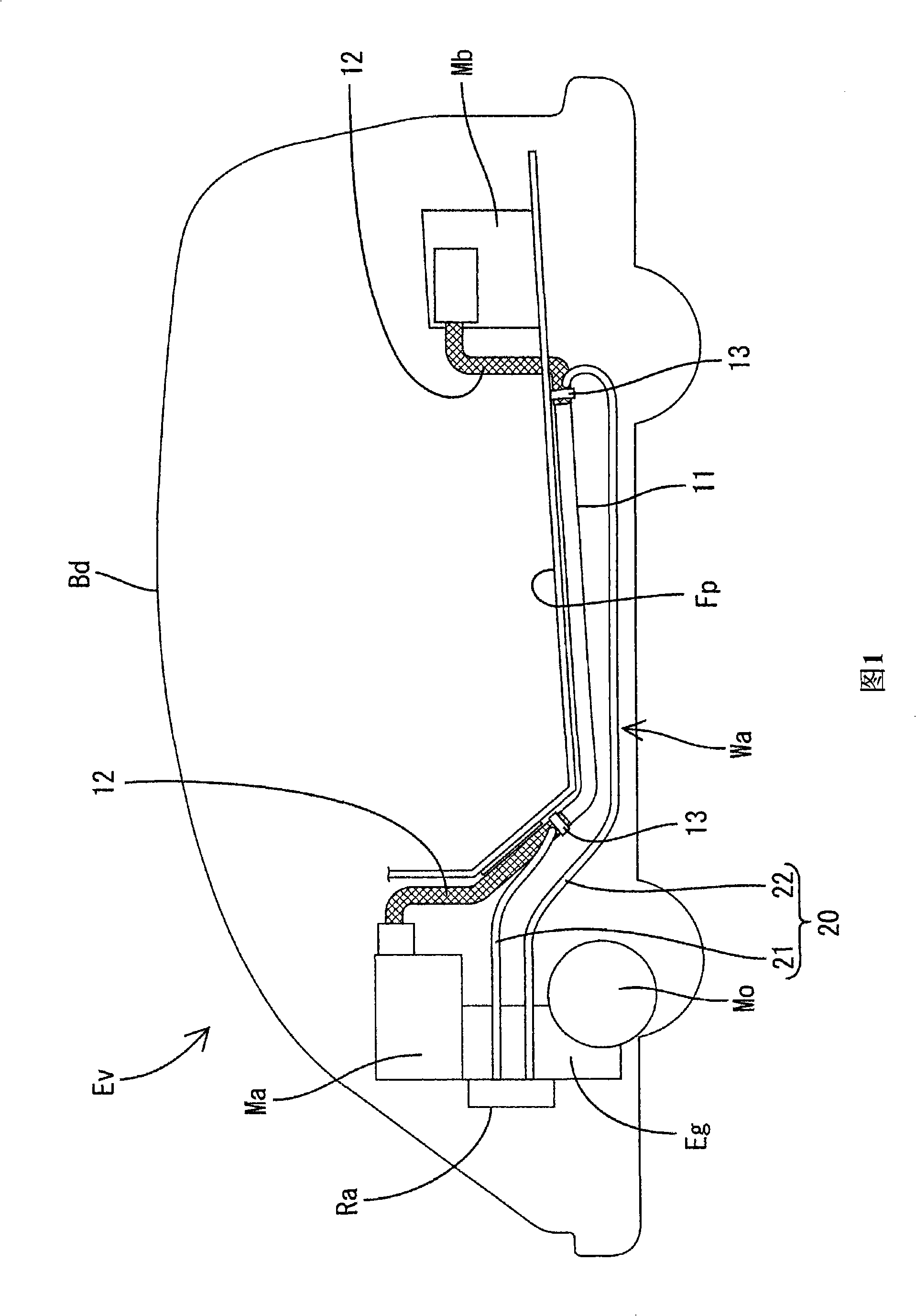
[0054] The following will refer to Figure 1 to Figure 5 A first embodiment according to the present invention will be described. The electric vehicle EV includes a body Bd and an engine room provided in front of the body Bd. Equipment Ma (for example, an inverter) and a gasoline engine Eg are accommodated in the engine room. The device Ma constitutes a drive circuit for driving the motor Mo. A device Mb (for example, a battery) constituting another drive circuit is mounted at the rear of the body Bd (for example, a trunk). A vehicle conductor Wa for a vehicle extends between the equipment Ma and the equipment Mb.
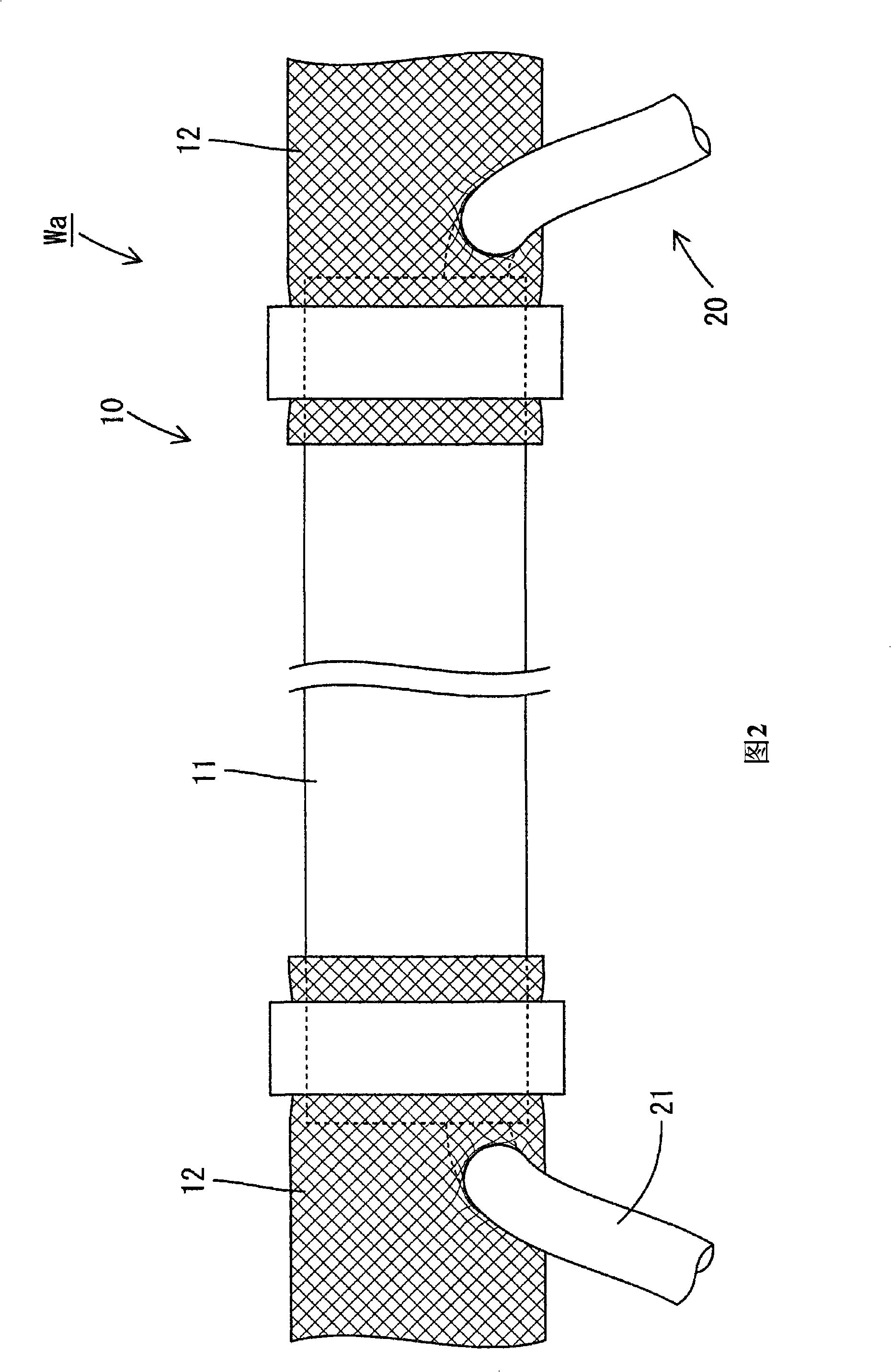
[0055] The vehicle conductor Wa includes a cylindrical electromagnetic shield 10 having a concentrated electromagnetic shielding function, a cooling pipe 20 having a heat dissipation function, and three electric wires 30 inserted in the shield 10 .
[0056] The shield 10 includes a protective duct 11 and a flexible tube 12 . The protection duct 11 is made of m...
no. 2 example
[0068] Next, reference will be made to Figure 6 and Figure 8 A second embodiment according to the present invention will be described. The vehicle conductor Wb includes an electric wire 40 having a structure different from that of the first embodiment. The other structures are similar to the first embodiment, so that descriptions of the configuration, functions, and effects are omitted.
[0069] The cross-section of each electric wire 40 is rectangular as a whole. Specifically, the section of each wire 40 is roughly I-shaped, and its long side is much larger than its short side. Each electric wire 40 has a long and thin plate shape (strip plate shape or flat plate shape) as a whole. The conductor portion 41 included in each electric wire 40 is a rectangular conductive portion having a rectangular transverse cross-sectional shape. The insulating resin jacket 42 surrounding each conductive portion 41 has a rectangular frame sectional shape. The electric wire 40 is helicall...
no. 3 example
[0076] will then refer to Figure 9 A third embodiment according to the present invention will be described. The vehicle conductor Wc according to the present embodiment includes holding means for holding the electric wire 30 in a state of being in contact with or close to the outer periphery of the cooling pipe 50 . The form of the holding means differs from the corresponding means according to the first embodiment. Other structures are similar to those of the first embodiment, and thus are denoted by the same reference numerals, and descriptions of structures, functions, and effects are omitted.
[0077] The cooling pipe 50 according to the present embodiment includes a pipe body 51 and three grooved holders 52 (retainers as one element of the present invention). The cross section of the pipe body 51 is circular and allows cooling water to flow therethrough. The grooved holders 52 are formed on the outer circumference of the tube body 51 and spaced apart from each other b...
PUM
 Abstract
Description
Claims
Application Information