
Orbit geometry parameter image measuring device and method for substituting chord wire method

A geometric parameter, camera measurement technology, applied in the field of digital camera measurement and railway engineering, can solve problems such as difficult system integration, complex measurement structure, large measurement error, etc., to achieve the effect of improving measurement accuracy, high degree of automation, and solving errors

Inactive Publication Date: 2010-04-07
NAT UNIV OF DEFENSE TECH
View PDF0 Cites 0 Cited by
  • Summary
  • Abstract
  • Description
  • Claims
  • Application Information

AI Technical Summary

Problems solved by technology

[0015] This method of measuring track geometric parameters based on strings often causes large measurement errors due to loose strings
This error will become larger as the measuring device is used longer
Moreover, each set of measuring devices can only measure one rail geometric parameter, the measurement structure is complex, and it is not easy to system integration
This string-based measurement method and measurement device can no longer meet the needs of the rapid development of my country's railways, and a new type of high-precision track geometric parameter measurement method and measurement device is urgently needed

Method used

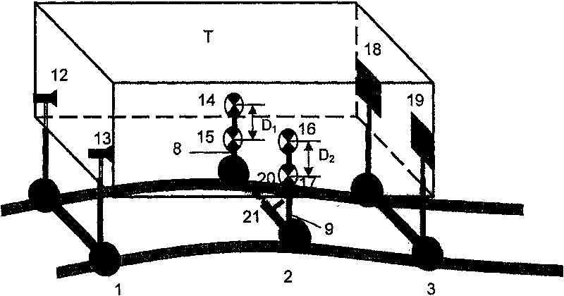

Image

  • Orbit geometry parameter image measuring device and method for substituting chord wire method
  • Orbit geometry parameter image measuring device and method for substituting chord wire method
  • Orbit geometry parameter image measuring device and method for substituting chord wire method

Examples


Embodiment Construction

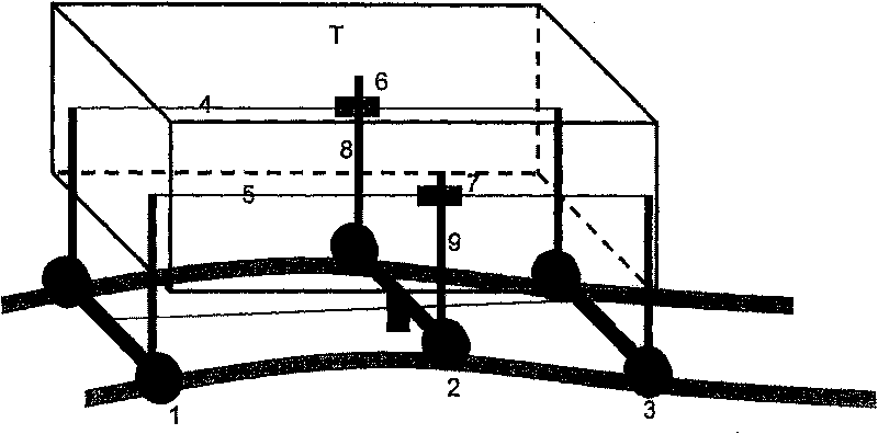
[0046] figure 1 Schematic diagram of the device for measuring the height of the track for the SRM-0832 tamping car produced by PLASSER&THEURER in Austria. The device for measuring height consists of the first operating trolley 1, the second operating trolley 3, the measuring trolley 2, the left detection rod 8 and the right detection rod 9 fixed on the measuring trolley 2, the left chord line 4 and the right chord line 5, the left high and low Sensor 6 and right high and low sensor 7 form. The first operating trolley 1, the second operating trolley 3, and the measuring trolley 2 are all placed on the track. The left and right detection rods are fixed on the corresponding track of the operation trolley 1, the left and right detection rods are also fixed on the corresponding track of the operation trolley 3, and the left and right measuring rods are fixed on the corresponding track of the measuring trolley 2. A left chord 4 is installed between the left detection rods, a right...


PUM


Abstract

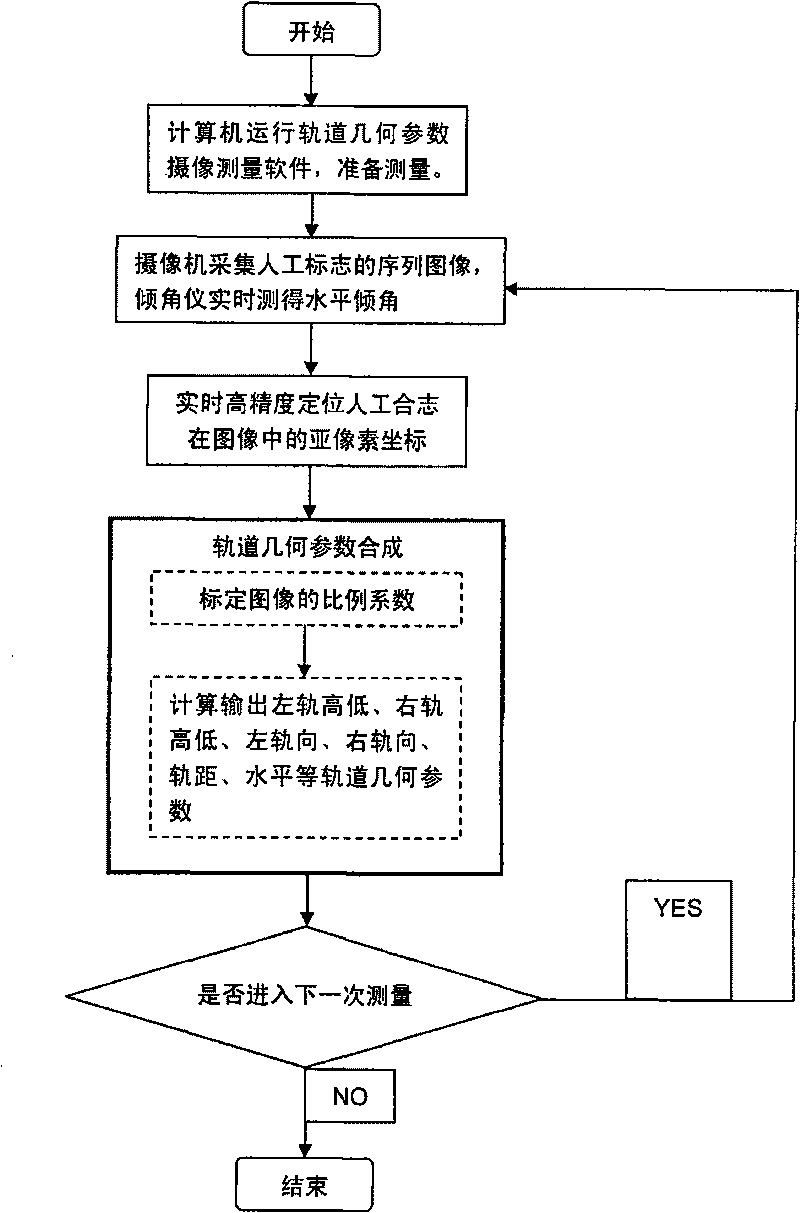
The invention discloses a video measuring device and method by track geometric parameters instead of the chord-line method, comprising a measuring car for track videos, two video cameras, a small measuring car, a dynamic electronic inclinometer, and a computer. Reference marks are made on the measuring car for track videos, and marks to be measured are made on the small measuring car. The measuring method is as follows: two video cameras are respectively used to collect the sequential images of marks to be measured and reference marks; the dynamic electronic inclinometer is used to measure thelevel dip angles; sub-pixel location is carried respectively on the marks to be measured and the reference marks; according to the sub-pixel coordinate of geometric centers of the marks to be measuredand the reference marks and according to the synthetic method of track geometric parameters, height, track direction, track gauge, and level are calculated and results are output at real time. The vi deo measuring device and method has the advantages of thoroughly solving the measurement errors due to looseness of chord-line in the general measurement method, improving the measuring accuracy, facilitating the reconstruction and lowering the cost.

Description

technical field [0001] The invention relates to the fields of digital camera measurement and railway engineering, and further refers to a camera measurement method for measuring track geometric parameters instead of the chord method. Background technique [0002] Under the action of long-term train operation and natural conditions, the railway line will inevitably be deformed and damaged. In order to ensure the safe, stable and fast operation of trains and prolong the service life of each component of the line, it is necessary to strengthen the maintenance of the railway. Accurate measurement of track geometric parameters is the premise of railway construction acceptance and maintenance. [0003] Common orbital geometry parameters include: [0004] ●Gauge: the distance between the inner sides of two rails in the same cross-section of the rails. [0005] ●Level: the height difference between two rail tops in the same rail section. [0006] ●Height: Also known as front and ...

Claims


Application Information

Patent Timeline
Patent Type & Authority Patents(China)
IPC IPC(8): B61K9/08G01B11/14G01B11/02G01B11/00
Inventor 于起峰伏思华邱志强王明志梁永辉
Owner NAT UNIV OF DEFENSE TECH
Learn More