Flange for connecting conveyer pipe

A technology of conveying pipes and flanges, which is applied in the field of accessories connecting conveying pipes, can solve the problems of inconvenient disassembly, high precision requirements, and difficult inspection of welding quality.

Inactive Publication Date: 2008-09-17
陈荣辉
View PDF1 Cites 3 Cited by
  • Summary
  • Abstract
  • Description
  • Claims
  • Application Information

AI Technical Summary

Problems solved by technology

[0002] At present, there are generally three ways to connect the conveying pipes: 1. Direct welding: direct welding should be carried out at the installation site. Generally, a series of processes such as trial assembly, welding, welding slag removal, and pickling must be carried out. It is inconvenient to disassemble after installation. , and the welding quality is not easy to check
2. Pipe joint connection: generally suitable for small-diameter delivery pipes, usually with welded pipe joints, ferrule-type pipe joints, flared pipe joints, etc. These methods are all connected by threaded connections made on the joint body and the pipe. High precision is required, the assembly process is complicated, the pipe is easy to be damaged, and the cost is high
3. Flange connection: Reliable work, easy assembly and disassembly, but it is often necessary to weld or cast flanges at the port of the delivery pipe, which requires high manufacturing precision and increases costs
This flange connection device has the following disadvantages: if the diameters of the two conveying pipes are different, especially if the difference is large, when the fluid flows through the joint surface of the two conveying pipes, the diameter will suddenly change, the energy will change suddenly, and it will be easily damaged Conveying pipes and flange devices, and it is easy to form a local increase in resistance coefficient, so it is not suitable for variable diameter connection of conveying pipes
In addition, the general flange connection device is not suitable for the connection of the delivery pipe with the port flanging

Method used


Image

  • Flange for connecting conveyer pipe
  • Flange for connecting conveyer pipe
  • Flange for connecting conveyer pipe

Examples


Embodiment Construction

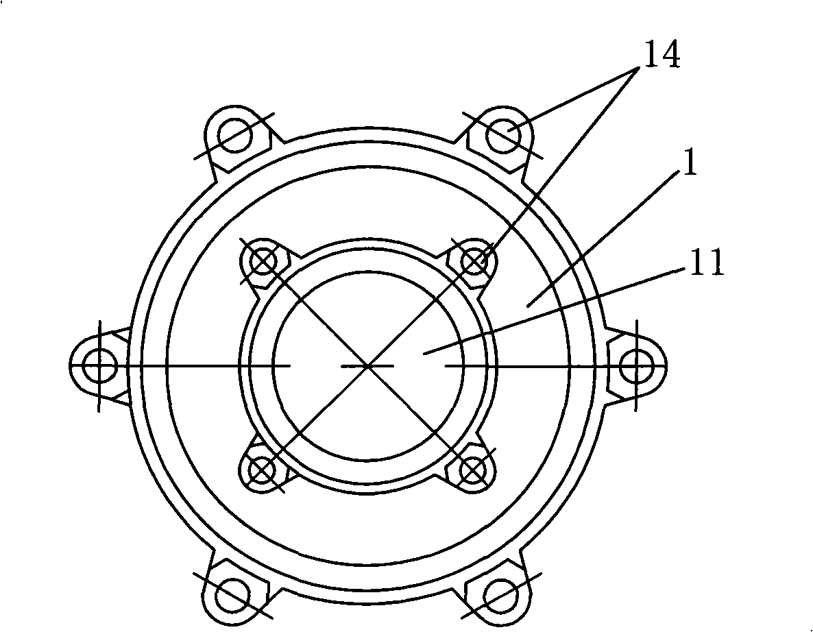
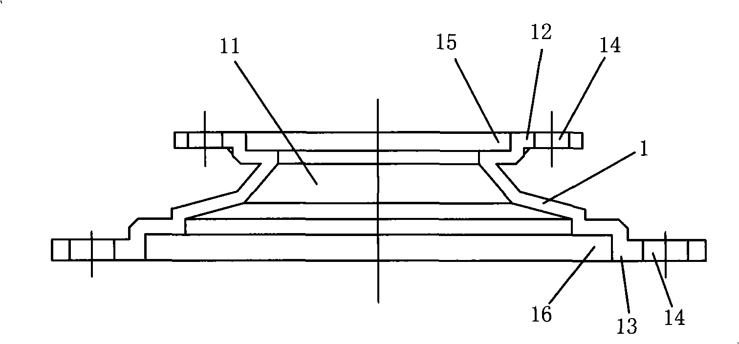
[0017] see figure 1 with 2 , the present invention is provided with body 1, and body is provided with center through hole 11, and both ends of body 1 are flanges, and 2 flanges 12 and 13 are respectively provided with 4 bolt holes 14 and 6 bolt holes 14. The central through hole 11 is a central through hole with tapering diameter. The two flanges 12 and 13 are respectively provided with grooves 15 and 16 to form double concave flanges. The axes of the grooves 15 and 16 coincide with the axis of the central through hole 11 . The central through hole 11 is a central through hole with tapering diameter.

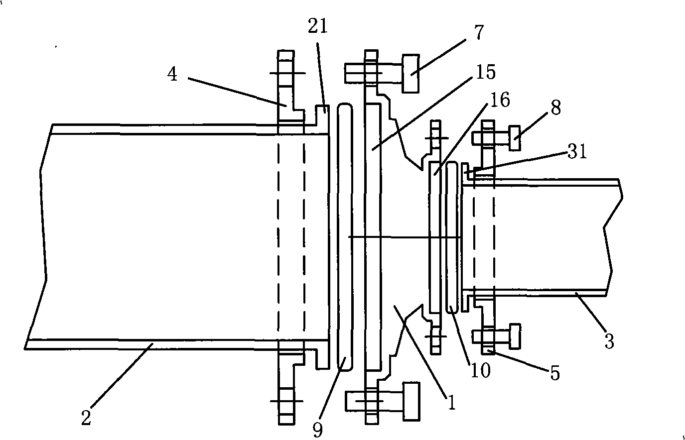
[0018] see image 3 , the ports of the two conveying pipes (straight-through pipes) 2 and 3 to be connected are flanged structures, and the ports of the conveying pipes 2 and 3 are provided with convex flange sleeves 4 and 5 respectively. When connecting, the flange sleeves 4 and 5 respectively press the port flanges 21 and 31 of the two conveying pipes 2 and 3 into the gro...


PUM


Abstract

A port flange of a delivery pipe relates to a part for connecting the delivery pipe, particularly a flange for connecting the delivery pipe. The invention provides a port flange which can be conveniently dismounted, slowly changed in diameter, and suitable for connecting a threaded port tubular product with a port flanging tubular product. The port flange comprises a body, and a central through hole processed on the body, wherein the two ends of the body are provided with flanges, and bolt holes are arranged on the flange.

Description

technical field [0001] The invention relates to a fitting for connecting delivery pipes, in particular to a flange for connecting delivery pipes. Background technique [0002] At present, there are generally three ways to connect the conveying pipes: 1. Direct welding: direct welding should be carried out at the installation site. Generally, a series of processes such as trial assembly, welding, welding slag removal, and pickling must be carried out. It is inconvenient to disassemble after installation. , and the welding quality is not easy to check. 2. Pipe joint connection: generally suitable for small-diameter delivery pipes, usually with welded pipe joints, ferrule-type pipe joints, flared pipe joints, etc. These methods are all connected by threaded connections made on the joint body and the pipe. High precision is required, the assembly process is complicated, the pipe is easy to be damaged, and the cost is high. 3. Flange connection: Reliable work, easy assembly and...

Claims


Application Information

Patent Timeline
Patent Type & Authority Applications(China)
IPC IPC(8): F16L23/032
Inventor 陈荣辉
Owner 陈荣辉
Why Eureka
Try Eureka