
Keyboard device for playing music automatically

A keyboard device and automatic performance technology, applied in the direction of automatic musical instruments, stringed instruments, instruments, etc., to achieve the effect of reducing the number of parts, reducing manufacturing errors, and enhancing durability

Inactive Publication Date: 2011-11-16
YAMAHA CORP
View PDF1 Cites 0 Cited by
  • Summary
  • Abstract
  • Description
  • Claims
  • Application Information

AI Technical Summary

Problems solved by technology

In this device, if there is a misalignment between the position of the push rod and the position where the hammer body should abut against the push rod, it will also have the same problem as above.

Method used


Image

  • Keyboard device for playing music automatically
  • Keyboard device for playing music automatically
  • Keyboard device for playing music automatically

Examples


no. 1 Embodiment approach

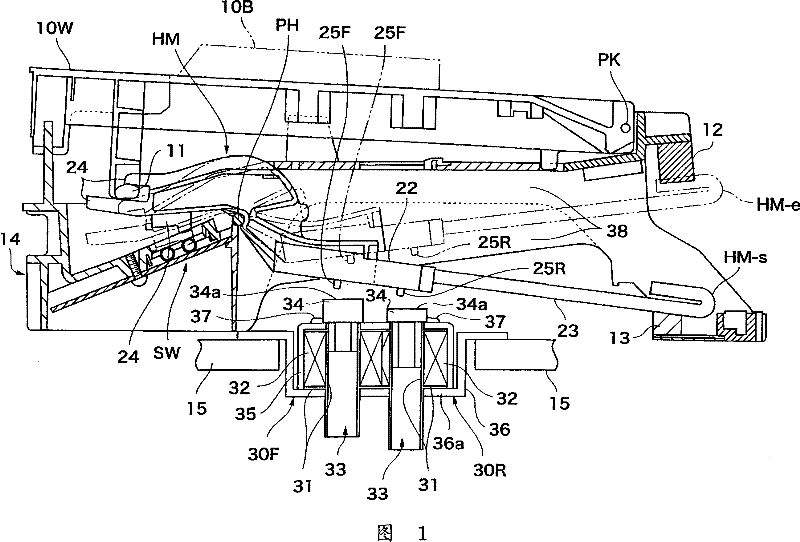
[0031] figure 1 It is a cross-sectional view of the keyboard device for automatic performance according to the first embodiment of the present invention.

[0032] This keyboard device is suitable, for example, for an electronic keyboard musical instrument that can be played automatically. This keyboard device is formed by supporting a plurality of keys 10 and hammer bodies HM corresponding to the respective keys 10 on the frame 14 . The key 10 is pressed down, and the key 10 is centered on the key rotation fulcrum PK and freely rotates in the up and down direction. There are a plurality of white keys 10W and black keys 10B as keys 10 . Next, connect the player side of this keyboard unit ( figure 1 left) is called "front". A hammer driving portion 11 is provided in the key 10 .

[0033] A hammer HM corresponding to each key 10 is arranged below each key 10 . Each hammer body HM is free to rotate around its respective hammer body rotation axis PH. In addition, the engagin...

no. 2 Embodiment approach

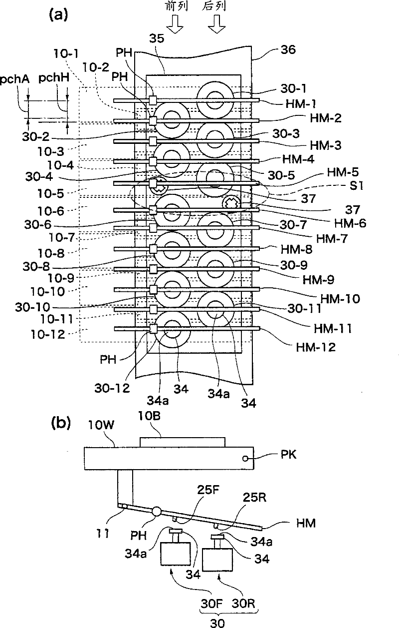
[0071] Image 6 (a) is a plan view of one octave of the driver portion in the keyboard device for automatic performance according to the second embodiment of the present invention. Image 6 (b) is a schematic diagram showing the key driving mechanism of the present keyboard device.

[0072] In the first embodiment, a keyboard device having the hammer HM was described as an example, and in the second embodiment, a configuration in which the key 10 is directly driven by the driver 30 without the hammer HM was described as an example.

[0073] like Image 6 As shown in (b), the key 10 is free to rotate in the vertical direction around the key rotation fulcrum PK2. like Image 6 As shown in (b) as an example, the protrusions 25F, 25R provided on the hammer HM in the first embodiment are provided on the lower surface of the rear end portion of the key 10 . The driver 30 is arranged below the protruding portion 25, the above-mentioned configuration is the same as that of the fir...


PUM


Abstract

The invention supplies a keyboard device for automatic performance, which reduces the incorrectness of the key drive due to the manufacturing error or time change. A hammer (HM) corresponding to each key (10) is collocated to link with the key (10); a driver (30) is set relatively to each hammer (HM). A projecting driven part, namely a bulge (25) is respectively set downwards at the front lateraland the rear lateral of the base (22) of the hammer (HM). The driver (30) is coiled with a solenoid (32) around the spool (31). The push rod (33) can move to and fro in the spool (31). The disc driving part (34) forms a whole at the upper part of the push rod (33). The upper surface of the driving part (34) forms a flat surface (34a). When the driver (30) drives the hammer (HM), the flat surface (34a) of the driving part (34) resists the top end (25a) of the projecting part (25).

Description

technical field [0001] The present invention relates to a keyboard device for automatic performance that utilizes the driving force of a driving member to drive keys. Background technique [0002] Conventionally, there is known a keyboard device for an automatic performance that realizes an automatic performance by driving keys by pressing the keys using the driving force of a driving member (Patent Document 1 below). [0003] In the device, the keys can freely swing around the key fulcrum, and corresponding to each key, a solenoid as a driving part is provided. The solenoids are arranged in a staggered manner in two rows along the key arrangement direction. The top end of the push rod arranged inside each solenoid is driven by pushing the lower surface of the rear end portion of the key from bottom to top, thereby driving the corresponding key in the direction of pressing the key. [0004] Patent Document 1: Japanese Utility Model Patent No. 2555777 [0005] However, due...

Claims


Application Information

Patent Timeline
Patent Type & Authority Patents(China)
IPC IPC(8): G10F1/02G10C3/12
CPCG10H1/346
Inventor 清水元英
Owner YAMAHA CORP
Learn More