Accelerometer Control Systems

a control system and accelerator technology, applied in the direction of automatic control, process and machine control, instruments, etc., can solve the problems of introducing uncertainties into the measurement of acceleration, non-linearity in measurement, and restricted range of g values to be measured, so as to maintain sensitivity

Active Publication Date: 2012-05-10
ATLANTIC INERTIAL SYST
View PDF5 Cites 26 Cited by
  • Summary
  • Abstract
  • Description
  • Claims
  • Application Information

AI Technical Summary

Benefits of technology

[0004]It is an object of the invention to provide a control system for an accelerometer of the variable capacitance typ

Problems solved by technology

Problems which arise are firstly that only a restricted range of g values may be measured, due to saturation of the charge amplifier.
Secondly, there is a problem of non-linearity in measurements, being caused by temperature var

Method used


Image

  • Accelerometer Control Systems
  • Accelerometer Control Systems
  • Accelerometer Control Systems

Examples


Embodiment Construction

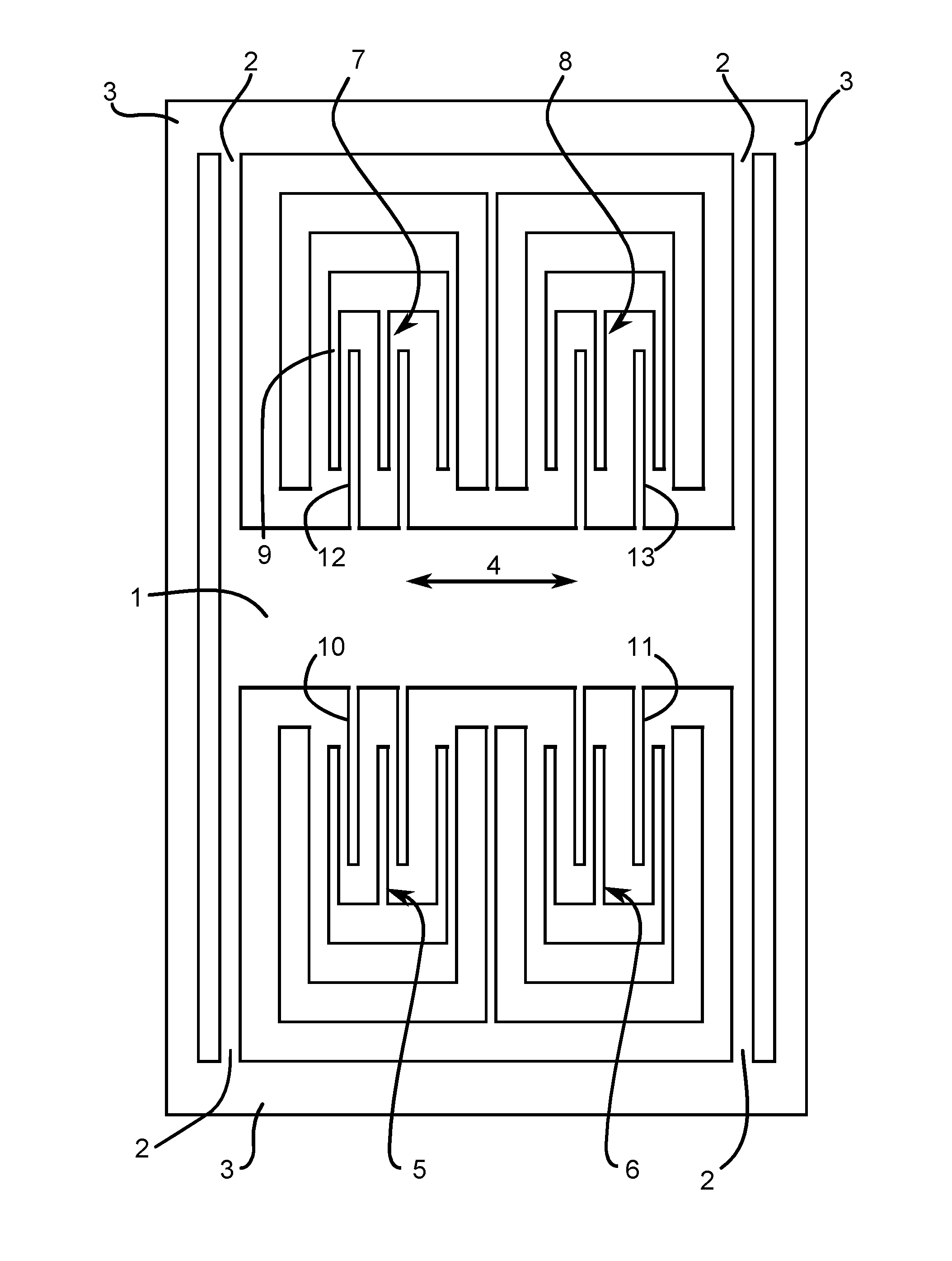
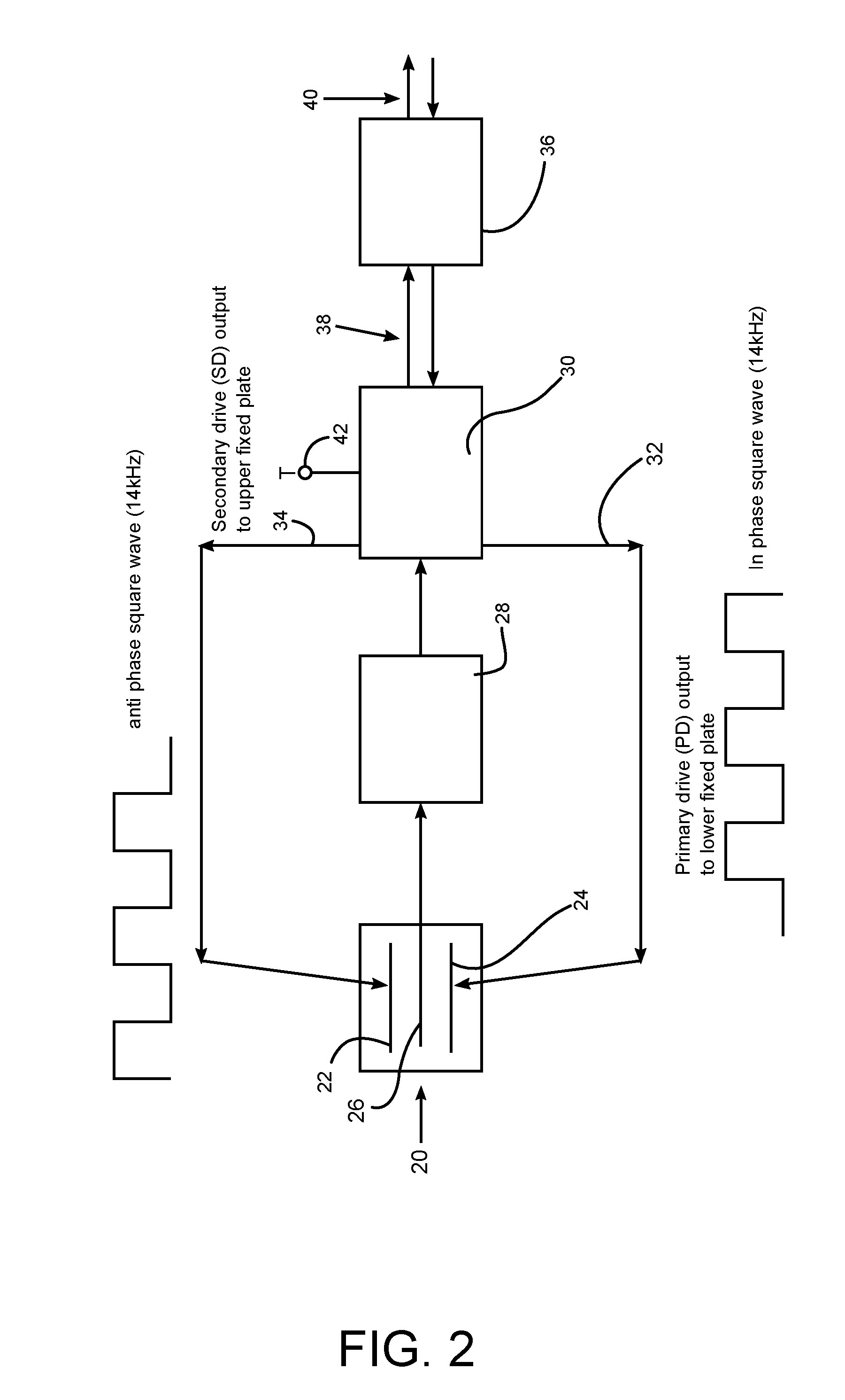
[0021]Referring now to FIG. 2 of the drawings, an open loop accelerometer control system is shown including autoranging and non-linearity compensation functions. An accelerometer 20 is of the variable capacitance type, and may be constructed as a MEMS device as shown in FIG. 1, with upper and lower fixed capacitor plates 22, 24 and a movable proof mass plate 26. Proof mass 26 provides an output signal, which represents acceleration as detected by the accelerometer, and this signal is coupled to a charge amplifier 28, which is physically mounted on proof mass 26 (a charge amplifier being a circuit whose equivalent input impedance is a capacitance that provides a very high value of impedance at low frequencies). Amplifier 28 is coupled to an ASIC 30. The ASIC provides primary drive (PD) and antiphase secondary drive (SD) square wave drive signals 32, 34, at 14 kHz frequency, to respective plates 24, 22. In this embodiment, there are two possible values of drive signal amplitude, 2.5 V...


PUM


Abstract

An accelerometer open loop control system comprising a variable capacitance accelerometer having a proof mass movable between fixed capacitor plates, drive signals applied to the capacitor plates, a charge amplifier amplifying an accelerometer output signal representing applied acceleration, and an autoranging facility for monitoring the output signal, and for adjusting the drive signals in dependence on the output signal in order to restrict the amplitude of the accelerometer output signal, thus maintaining sensitivity of the accelerometer while permitting response to a wide range of g values. Corrections are applied by means of look up tables to compensate for inaccuracies arising from movement of the proof mass and temperature variations.

Description

FIELD OF THE INVENTION[0001]The present invention relates to accelerometer control systems.BACKGROUND ART[0002]Accelerometers, which are responsive to linear acceleration, are disclosed in U.S. Pat. Nos. 7,047,808 and 7,267,006. The described accelerometers are of the variable capacitance type, comprising a proof mass movable between fixed capacitor plates. They are constructed in silicon as MEMS devices, with a proof mass on a thin suspension so as to be movable, which is sandwiched between two fixed capacitor plates each at a small gap from the proof mass. Under the effect of acceleration on the accelerometer one gap increases and the other decreases to give a differential output signal. The construction includes interdigitated fingers, which increase sensitivity and increase gain to get the noise down. This construction is shown in FIG. 1, which includes a plate-like proof mass 1, four flexible mounting legs 2 co-planar with the proof mass 1, which are mounted between the mass 1 ...

Claims


Application Information

Patent Timeline
IPC IPC(8): G01P21/00G06F19/00G16Z99/00
CPCG01P15/125G05B24/02G01P2015/0814G06F19/00G06F17/40G01P21/00G16Z99/00
Inventor MALVERN, ALAN
Owner ATLANTIC INERTIAL SYST
Why Eureka
Try Eureka