Dissolved oxygen sensor

a technology of dissolved oxygen and sensors, applied in the field of oxygen sensors, can solve the problems of increasing the corrosion of materials involved in the process, unable to adapt electromechanical sensors to ultra-high purity environments, and difficult to repurpose electrochemical sensors that use relatively large metal probes, etc., to achieve the effect of small footprint, small sensor footprint, and reduced size or footprin

Active Publication Date: 2015-05-07
ENTEGRIS JETALON SOLUTIONS
View PDF5 Cites 11 Cited by
  • Summary
  • Abstract
  • Description
  • Claims
  • Application Information

AI Technical Summary

Benefits of technology

[0011]By aligning these components the size or footprint of the sensor may be reduced while sensitivity is maintained. In particular, the arrangement of the components of dissolved oxygen sensors according to embodiments herein allows such oxygen sensors to be both compact and suitable for use in ultra-high purity environments. More specifically, by aligning the components of the optical probe, including the optical reception guide, photodiode, reference light source and PCB, the footprint of the sensor may be reduced. Moreover, the use of an optical carrier that allows optical and electrical separation of the excitation light source from the reference light source while allowing an optical reception guide and optical transmission guide to share at least a portion of the same path through the optical probe may also contribute to a sensor with a small footprint or otherwise reduced size. By achieving a sensor with reduced size and ultra-high purity compatibility, embodiments of such a sensor may be suitable for use in a wide variety of process where previously DO sensors were unable to be utilized or did not meet the performance or serviceability desires of operators of those processes.
[0012]Additionally by configuring these embodiments such that no portion of the optical probe is within the fluid flow path, the fluid flow path may be scaled to substantially any desired diameter while still maintaining laminar flow increasing the environments in which such a sensor may be utilized. Moreover, as only the window of such a sensor may be in contact with the fluid, electronic and other components of the sensor may be effectively sealed against fluid intrusion, extending the lifetime of the sensor in a harsh environment, in which caustic and molecularly small chemicals may be used.
[0013]In certain embodiments, the window utilized may be high strength, optically transparent material that exhibits a high degree of thermal conductivity such as sapphire or diamond. By using such materials for the window a high degree of sealing force may be utilized. To apply such a sealing force an annular retainer or retainer nut may be utilized in certain embodiments. Such an annular retainer nut may be threaded around its outer circumferences such that it can be screwed into a threaded wall of a body of the sensor above the window. The tip of the optical probe can reside or otherwise be disposed in the center of the retainer nut such that it is held a working distance from the window. The use of such a retainer or retainer nut may allow easy replacement of the luminophor (e.g., easy removal of the window without having to touch or remove any components within the optical probe itself), increasing the field serviceability of such a sensor and reducing expense by reducing process downtimes.
[0014]In conjunction with such serviceability and cost reduction goals, embodiments of the sensor may provide an indicator when the luminophor may need replacement. In particular, in certain embodiments the magnitude of light emitted by the luminophor may be monitored to determine if the luminophor should be replaced. In this manner, accurate functioning of dissolved oxygen (DO) sensor may be maintained while avoiding the unnecessary expense of frequent luminophor replacement. More specifically, a baseline magnitude for the luminophor may be determined and stored with respect to the DO sensor. This baseline magnitude may be an absolute value that may be user determined and set or may be determined during a calibration process and may be indicative of the maximum intensity of light emitted by the luminophor. During a measurement cycle (which may be every measurement cycle, a designated measurement cycle performed under certain conditions, etc.) a magnitude of the light emitted by the luminophor may be determined and compared to this baseline magnitude. If the determined magnitude for the light emitted by the luminophor during that measurement cycle is not within some threshold of the baseline magnitude an alarm may be generated. This alarm may signal operators (e.g., of a process) employing such a DO sensor that the luminophor of the sensor needs replacement and operators may take a wide variety of actions based on the alarm, including shutting down a process, replacing the luminophor, etc.
[0015]To increase the sensitivity or accuracy of embodiments of such a sensor the optical probe may separate certain functionality or components to prevent electrical optical crosstalk. In particular, according to certain embodiments, the optical probe may include an optical carrier disposed within an optical sleeve. The excitation light source of the DO sensor may be on one side of the optical carrier while the reference light source, photodiode and optical reception carrier configured to conduct light emitted by luminophor to the photodiode may be separated from the excitation light, by placing these components on the other side of the optical carrier or by encasing them in various chambers or bores of the optical carrier. Thus, the combination of the optical carrier (and the components thereon) and the optical sleeve encasing the optical carrier serves to electrically and optically isolate the components of the sensor.

Problems solved by technology

For example, the presence of oxygen in semiconductor manufacturing processing may increase corrosion of materials involved in the process (e.g., copper used in a plating process) among other problems.
Attempts to adapt electromechanical sensors to ultra-high purity environments has proved well-nigh impossible because it is extremely difficult to re-purpose electrochemical sensors that use relatively large metal probes (e.g., stainless steel or aluminum) originally intended as dip probes to sample dissolved oxygen content in rivers, streams, and lakes to ensure minimum oxygen concentrations levels for wildlife to the task of detecting the sub-part per billion (e.g., 1 part in 109) concentrations of oxygen required for use in semiconductor manufacturing processes, food and drug processes, or other ultra-high purity environments.
From an industry perspective such attempts have heretofore been failures.
This failure is due in no small part to the very nature of electrochemical sensors.
The insertion of these metal probe tips, for example in the process fluid of a semiconductor manufacturing process, serves to contaminate the process fluid in which it is inserted, making the use of such electrochemical sensors incompatible with the materials and processes in which they are being utilized and the standards for those processes.
As such electrochemical sensors cannot be used with the caustic fluids that may be utilized in these ultra-high purity environments.
In other words, there may a fundamental materials incompatibility between the materials of such electro chemical sensors and the fluids used in ultra-high purity environments that prevents adherence to standards that define those environments.
Moreover, the presence of the probe tips of electrochemical sensors in the fluid serves to disrupt the laminar flow of the fluid, agitating the fluid and causing dead legs in the fluid flow path.
These disruptions may, in turn, cause unwanted side effects such as bubbles, or variations in dispense rates, etc. that negatively affect the process in which the fluid is being utilized.
Other problems with the use of these electrochemical sensors include the fact that electrochemical sensors may have a relatively large form factor and be ill-designed for use in the high pressure flow rates that are sometimes utilized in ultra-high purity environments.
Thus, in many cases, such electrochemical sensors may not be used at all in the compact installations sometimes utilized in ultra-high purity environments or may experience a high rate of failure due to leakage or corrosion resulting from poor internal sealing.

Method used


Image

  • Dissolved oxygen sensor
  • Dissolved oxygen sensor
  • Dissolved oxygen sensor

Examples


Embodiment Construction

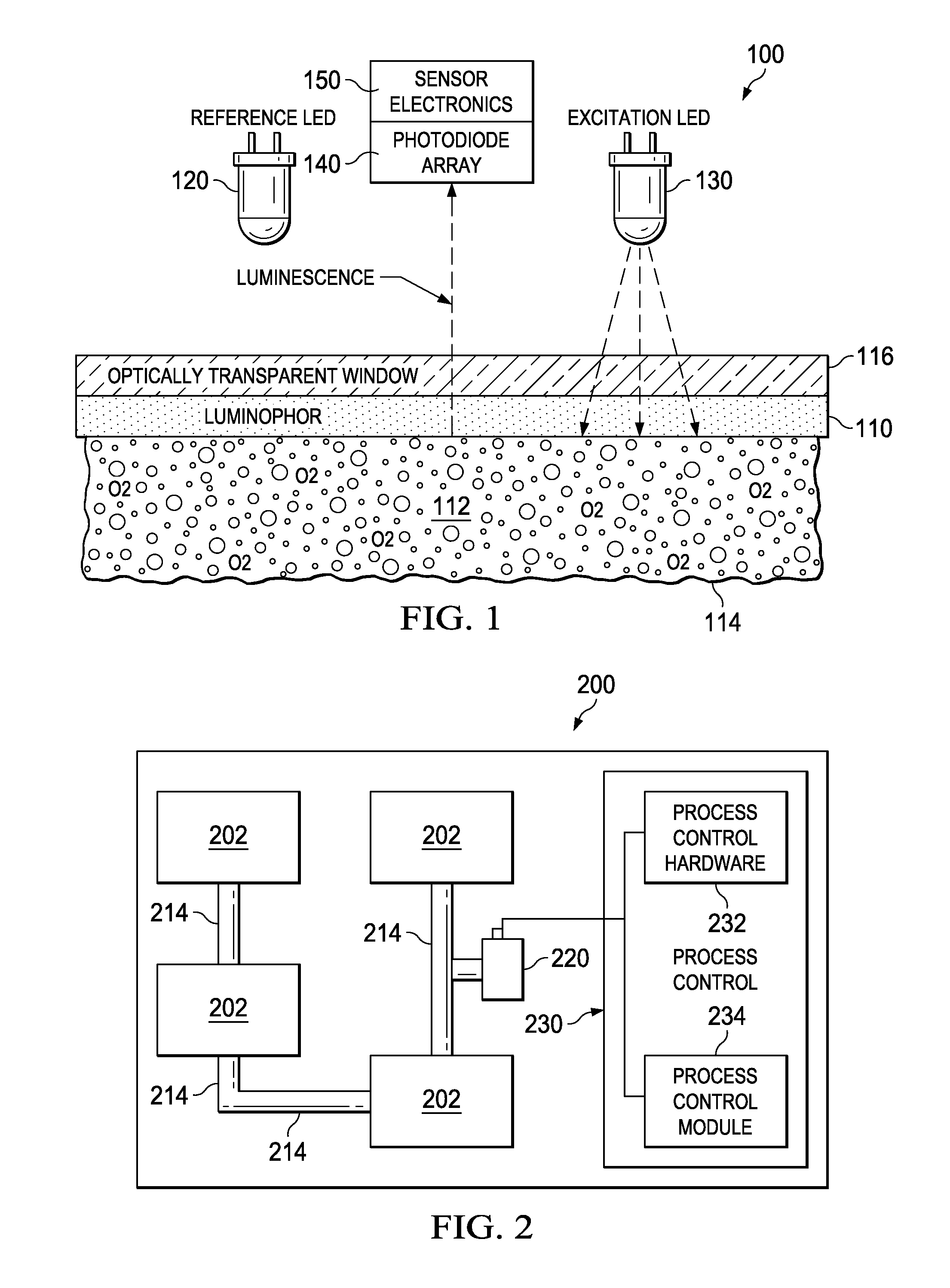
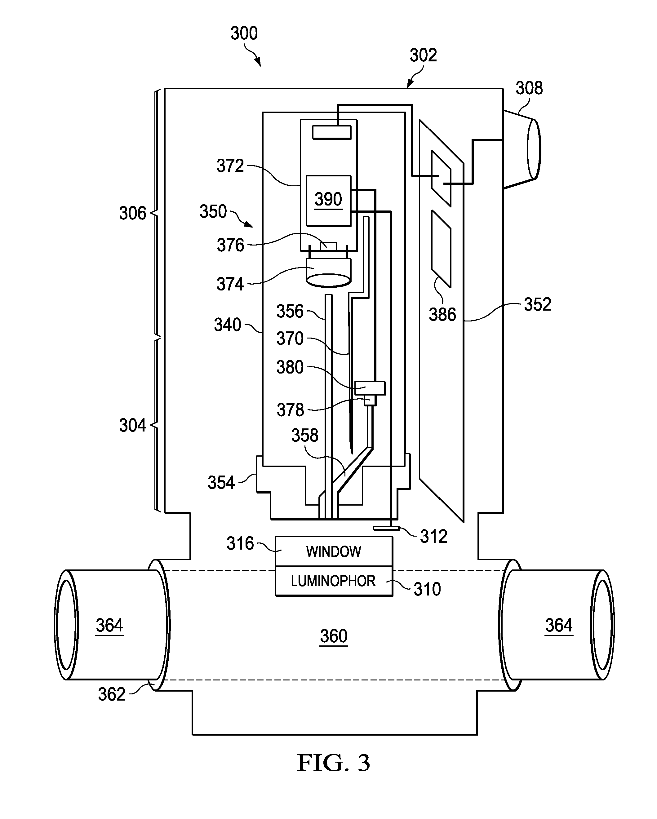
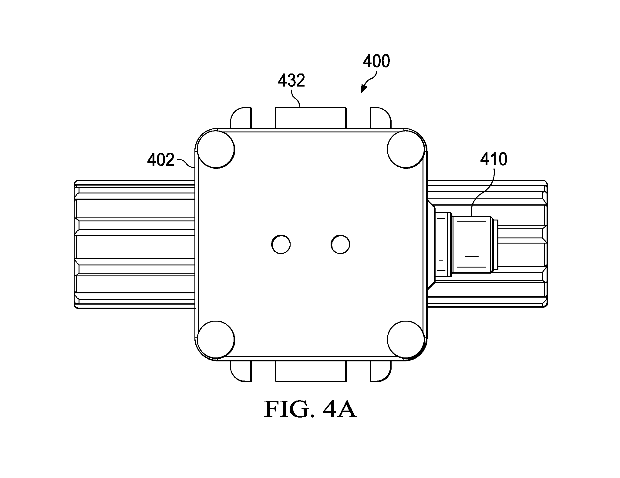
[0031]The disclosure and the various features and advantageous details thereof are explained more fully with reference to the non-limiting embodiments that are illustrated in the accompanying drawings and detailed in the following description. Descriptions of well-known starting materials, processing techniques, components and equipment are omitted so as not to unnecessarily obscure the disclosure in detail. Skilled artisans should understand, however, that the detailed description and the specific examples, while disclosing preferred embodiments, are given by way of illustration only and not by way of limitation. Various substitutions, modifications, additions or rearrangements within the scope of the underlying inventive concept(s) will become apparent to those skilled in the art after reading this disclosure. As an example, it should be noted that embodiments as described herein relate to a dissolved oxygen sensor, however, other embodiments may equally well be utilized to measur...


PUM

PropertyMeasurementUnit
thresholdaaaaaaaaaa
thresholdaaaaaaaaaa
pressureaaaaaaaaaa

Abstract

Embodiments of a dissolved oxygen sensor are disclosed herein. Embodiments as disclosed herein may include a window of optically transparent material disposed in an opening in a fluid flow path, where a luminophor is attached to the side of the window exposed to the fluid in the flow path. An optical probe may be disposed opposite the window from the fluid flow path on an axis at an angle to the window fluid flow path. The optical probe includes an excitation light source for illumination of the luminophor and a reference light source. An optical reception guide is configured to conduct light from the luminophor to a photodiode adjacent to the end of the optical reception guide distal the window when the luminophor is illuminated by the excitation light source. The optical probe is configured to determine a measure of oxygen concentration of the fluid in the flow path. The optical reception guide and photodiode may be aligned on axis, where the axis may be substantially parallel with the axis on which the optical probe is aligned.

Description

RELATED APPLICATIONS[0001]This patent application claims a benefit of priority under 35 U.S.C. §119 to U.S. Provisional Patent Application Ser. No. 61 / 898,906 filed Nov. 1, 2013, entitled “Device And Method To Measure Sub Part Per Billion Concentration Of Dissolved Oxygen In Liquids”; U.S. Provisional Patent Application Ser. No. 61 / 899,605 filed Nov. 4, 2013, entitled “Device And Method To Measure the Concentration Of Dissolved Oxygen In Liquid”; and U.S. Provisional Patent Application Ser. No. 61 / 955,966 filed Mar. 20, 2014, entitled “Dissolved Oxygen Sensor And Auto-Detect End Of Life Of Light-Emitting Substance”, all of which are incorporated herein in their entirety by reference for all purposes.TECHNICAL FIELD[0002]This disclosure relates generally to oxygen sensors. More particularly, this disclosure relates to dissolved oxygen (DO) sensors. Even more specifically, this disclosure relates to sensitive, miniaturized DO sensors suitable for ultra-high purity environments.BACKGRO...

Claims


Application Information

Patent Timeline
Patent Type & Authority Applications(United States)
IPC IPC(8): G01N33/18
CPCG01N33/18G01N21/6408G01N21/643G01N21/77G01N21/85G01N33/1806G01N2021/6432G01N2021/7786A61B5/0833
Inventor MACHUCA, FRANCISCO JAVIERMONTGOMERY, KYLE WILLIAMCHIARELLO, RONALD PHILLIP
Owner ENTEGRIS JETALON SOLUTIONS
Why Eureka
Try Eureka