Systems and methods for tape flaw and splice avoidance in manufacturing

a technology of composite tapes and tape rolls, applied in the direction of liquid/solution decomposition chemical coating, mechanical control devices, instruments, etc., can solve the problems of tape length loss, similar problems, and inability to register flaws or splices in rolls of tapes,

Active Publication Date: 2007-05-03
THE BOEING CO
View PDF13 Cites 27 Cited by
  • Summary
  • Abstract
  • Description
  • Claims
  • Application Information

AI Technical Summary

Benefits of technology

[0005] The present invention is directed to systems and methods for avoidance of tape flaw, splices and roll ends in manufacturing, including the manufacturing of composite structures. Embodiments of systems and methods in accordance with the present invention may reduce the inaccuracies in referencing and tracking flaws, splices, and roll ends present in a tape, and may reduce downtime and associated costs, in comparison with the prior art.
[0007] In an alternate embodiment, a method of applying a tape onto a workpiece includes feeding the tape from a tape supply using a tape application assembly, and applying the tape onto the workpiece using the tape application assembly. Simultaneously with the feeding of the tape, the tape is monitored for a marker indicating a defect within the tape or the end of the roll, the marker being spaced apart along the tape from the defect or roll end such that the marker arrives prior to the defect or roll end. The method further includes detecting the marker, and avoiding the application of a portion of the tape that includes the defect onto the workpiece or where the end of roll would be encountered before reaching the end of the length of a course of tape.

Problems solved by technology

These splices can result in random and unpredictable process interruptions during lay up by a composite tape laying machine, causing down time during which the spliced section of the tape must be removed from the composite structure being manufactured.
Additionally, reaching the end the tape roll unexpectedly can cause similar problems.
For example, tape length can be lost and become unaccounted for by the flaw avoidance system.
This results in a loss of the measuring reference to the starting end of the tape and the inability to avoid tape splices, flaws and / or roll ends until manual adjustments are made.
However, these manual adjustments may be inaccurate and can contribute to further inability to avoid tape splices.

Method used


Image

  • Systems and methods for tape flaw and splice avoidance in manufacturing
  • Systems and methods for tape flaw and splice avoidance in manufacturing
  • Systems and methods for tape flaw and splice avoidance in manufacturing

Examples


Embodiment Construction

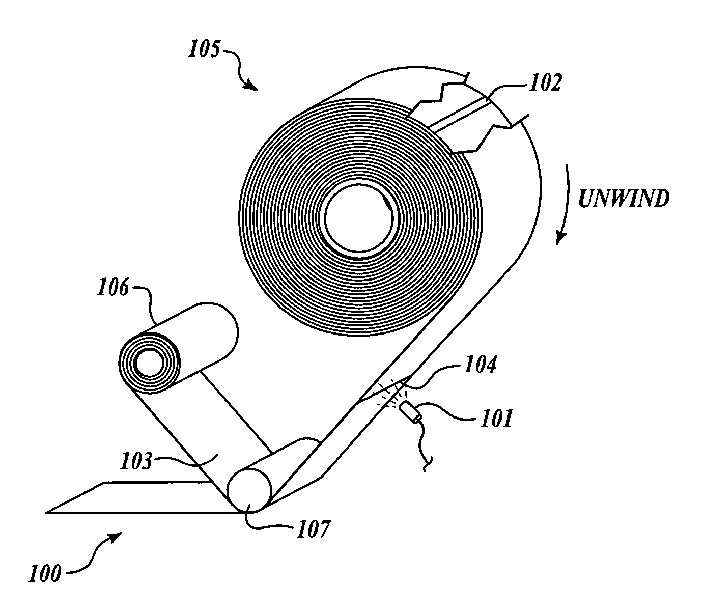
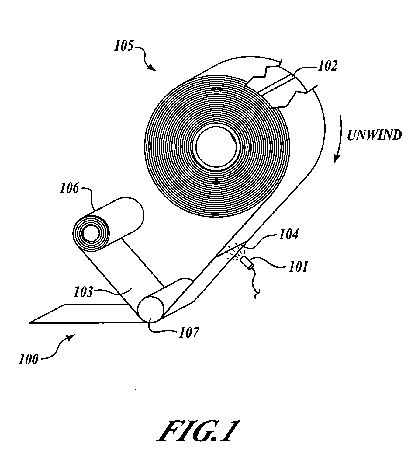
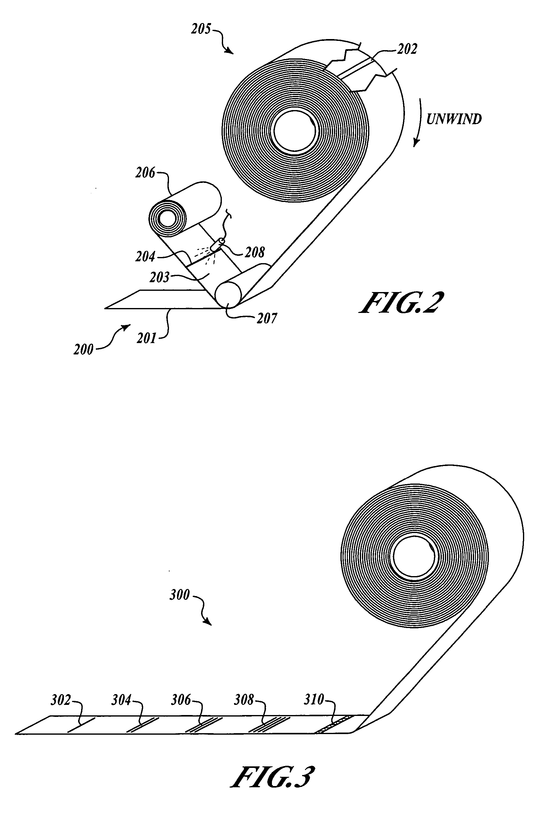
[0018] The present invention relates to systems and methods for avoiding tape flaws or splices in manufacturing, and for encountering and avoiding the end of a tape roll within a partially completed course of tape, including manufacturing of composite structures. Many specific details of certain embodiments of the invention are set forth in the following description and in FIGS. 1-9 to provide a through understanding of embodiments. The present invention may have additional embodiments, or may be practiced without one or more of the details described below.

[0019] Generally, embodiments of systems and methods in accordance with the present invention provide advance reference and tracking of tape flaws or splices as a tape is unwound during use for manufacturing. Thus, embodiments of the present invention may advantageously reduce the inaccuracies in referencing and tracking flaws or splices in a tape, and may improve efficiency and reduce costs associated with manufacturing componen...


PUM

PropertyMeasurementUnit
distanceaaaaaaaaaa
distanceaaaaaaaaaa
distanceaaaaaaaaaa

Abstract

Systems and methods for avoidance of tape flaw or splices in manufacturing are disclosed. In one embodiment, a method of applying a tape onto a workpiece includes feeding the tape from a tape supply using a tape application assembly, and applying the tape onto the workpiece using the tape application assembly. Simultaneously with the feeding of the tape, the tape is monitored for a marker indicating a defect within the tape, the marker being spaced apart along the tape from the defect such that the marker arrives prior to the defect. The method further includes detecting the marker, and avoiding the application of a portion of the tape that includes the defect onto the workpiece.

Description

FIELD OF THE INVENTION [0001] This invention relates generally to systems and methods for registering and avoiding flaws or splices in rolls of tape, and more specifically, to systems and methods for registering flaws or splices in composite tapes during manufacturing of composite structures. BACKGROUND OF THE INVENTION [0002] Composite structures are commonly manufactured by progressively building up the structure with a plurality of layers of thin composite tape (or tow) laid one layer upon another. Typically, the operation begins by laying one or more tapes onto a starting template or tool that has a configuration generally corresponding to the desired shape of the article to be produced. A tape placement head of a manufacturing system moves over the surface of the template, guiding the one or more tapes of composite material onto the template. The head usually makes repeated passes over the template in a defined pattern until the composite material is entirely collated, building...

Claims


Application Information

Patent Timeline
Patent Type & Authority Applications(United States)
IPC IPC(8): B32B37/00B32B38/00B32B41/00
CPCB29C70/30B29C70/386G01N21/89G01N2021/8472
Inventor KRAMP, ROBERT A.
Owner THE BOEING CO
Why Eureka
Try Eureka