Pipe cutting apparatus and method

a cutting apparatus and pipe technology, applied in the direction of tube shearing machines, saw chains, manufacturing tools, etc., can solve the problems of large cost of finding and fixing leakage, irregular beveled edges, etc., to facilitate the secure clamping of pipes, reduce the imprecision of pipe cutting and beveling, and enhance the safety of the apparatus

Active Publication Date: 2007-02-08
KAEHR LYLE D +1
View PDF18 Cites 30 Cited by
  • Summary
  • Abstract
  • Description
  • Claims
  • Application Information

AI Technical Summary

Benefits of technology

[0014] An advantage of the present invention is that by securely clamping the pipe it can reduce imprecision in the cutting and beveling of the pipe caused by warping in the pipe or slippage of a wet pipe. Features of the present invention that facilitate the secure clamping of the pipe, individually and in combination, include the use of a substantially equally-spaced three point support system, a clamping member with a biasing member and a strong and rigid frame formed by filling hollow structural members with a settable material that has cured into a rigid mass of material.
[0015] Another advantage of the present invention is that provides a two-part tool shield to enhance the safety of the apparatus.
[0016] Yet another advantage of the present invention is that it provides a power transmission system that transfers power from a motor mounted on a stationary frame to a pipe working tool mounted on a pivotal tool arm which does not require the use of multiple belts or a belt tensioning device.
[0017] Still another advantage of the present invention is that it provides a depth adjusting assembly that can be used to controllably adjust the depth of a bevel being formed in a pipe.

Problems solved by technology

The use of hand held cutting or grinding tools, however, will often result in an irregular beveled edge.
Oftentimes, the source of such leaks is a damaged or displaced gasket at the junction of two pipes.
The cost of finding and repairing such leaks can be very significant.

Method used


Image

  • Pipe cutting apparatus and method
  • Pipe cutting apparatus and method
  • Pipe cutting apparatus and method

Examples


Embodiment Construction

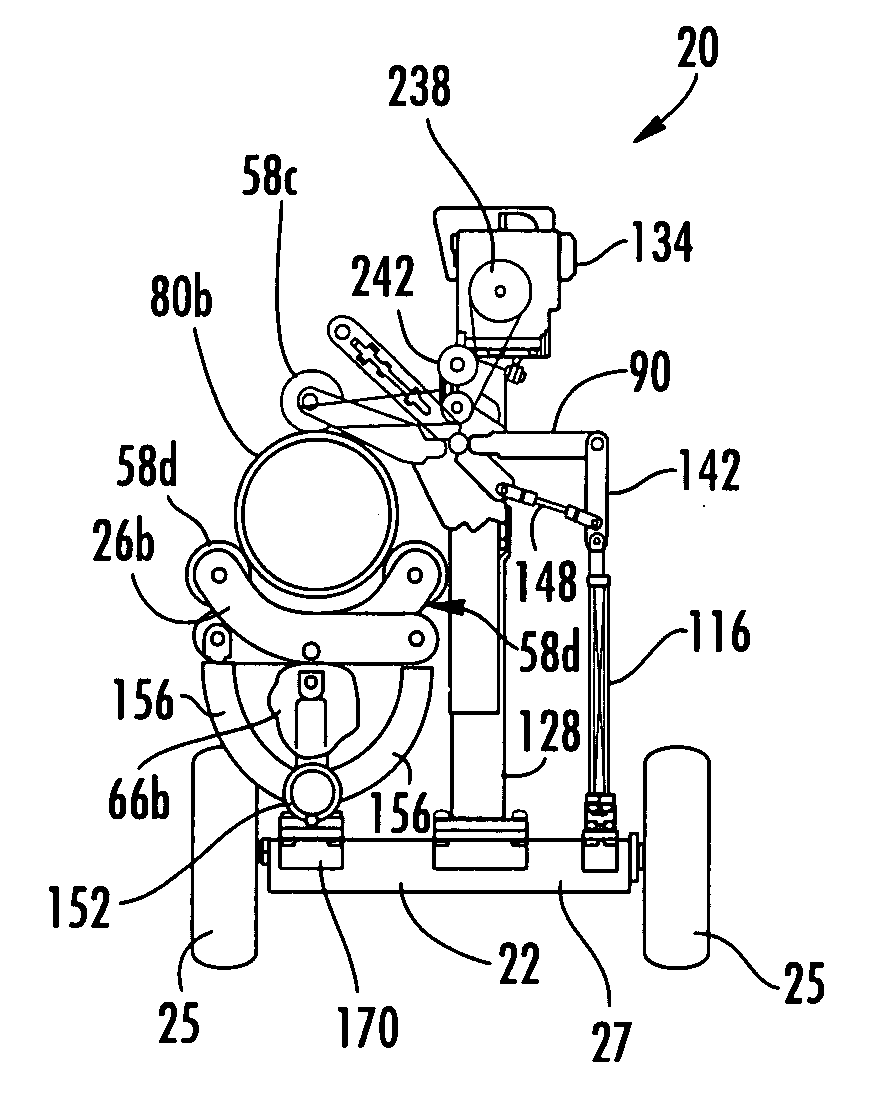
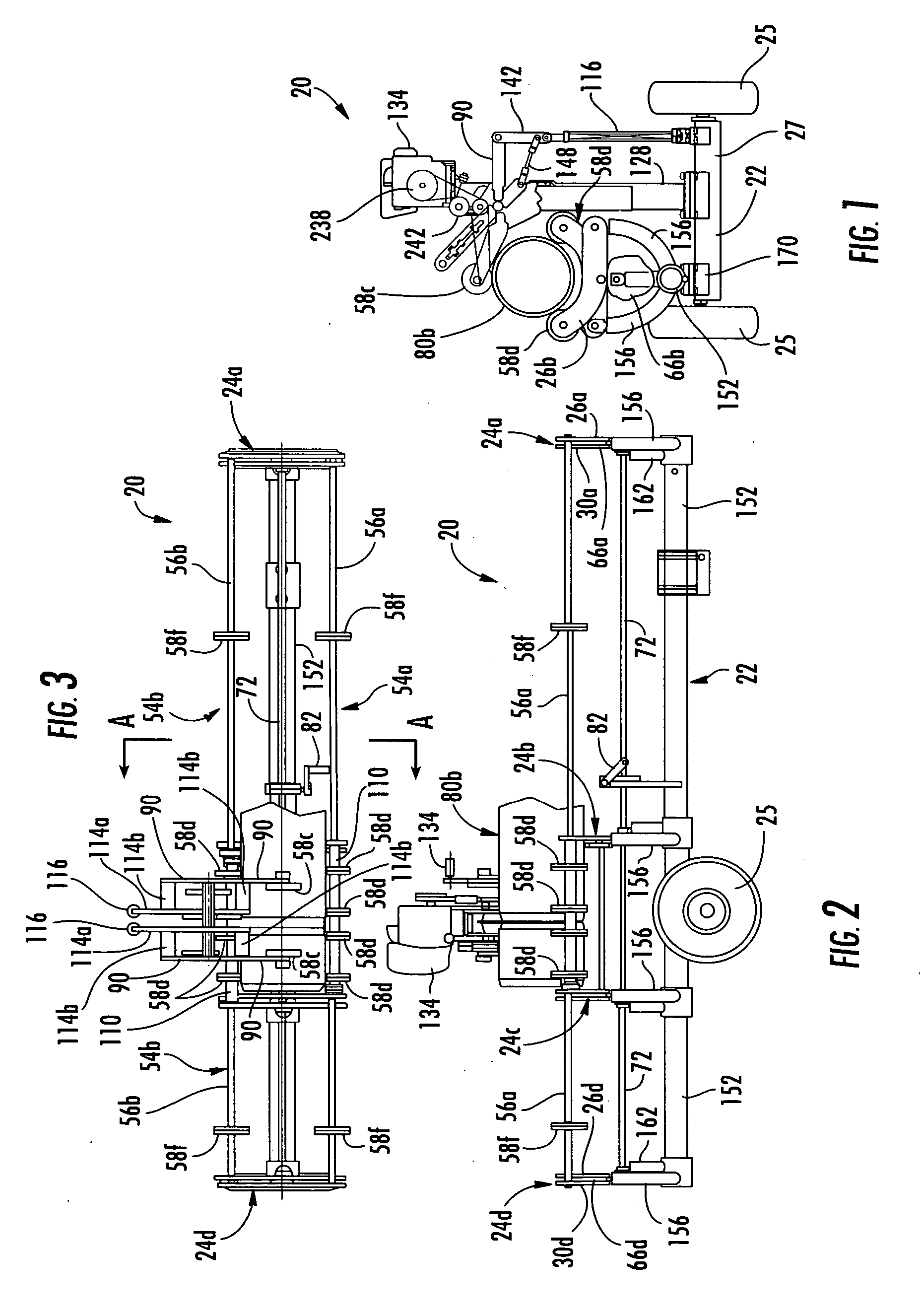
[0059] An overall view of a pipe cutting apparatus 20 in accordance with the present invention is shown in FIGS. 1-3. The illustrated pipe cutting apparatus, or pipe cutter, 20 has a structural frame 22 including a main beam 152 having pairs of bent arms 156 attached thereto at spaced locations along the length of main beam 152. Frame 22 also includes a lateral member 27 formed by the axle assembly housing and a vertical riser 128.

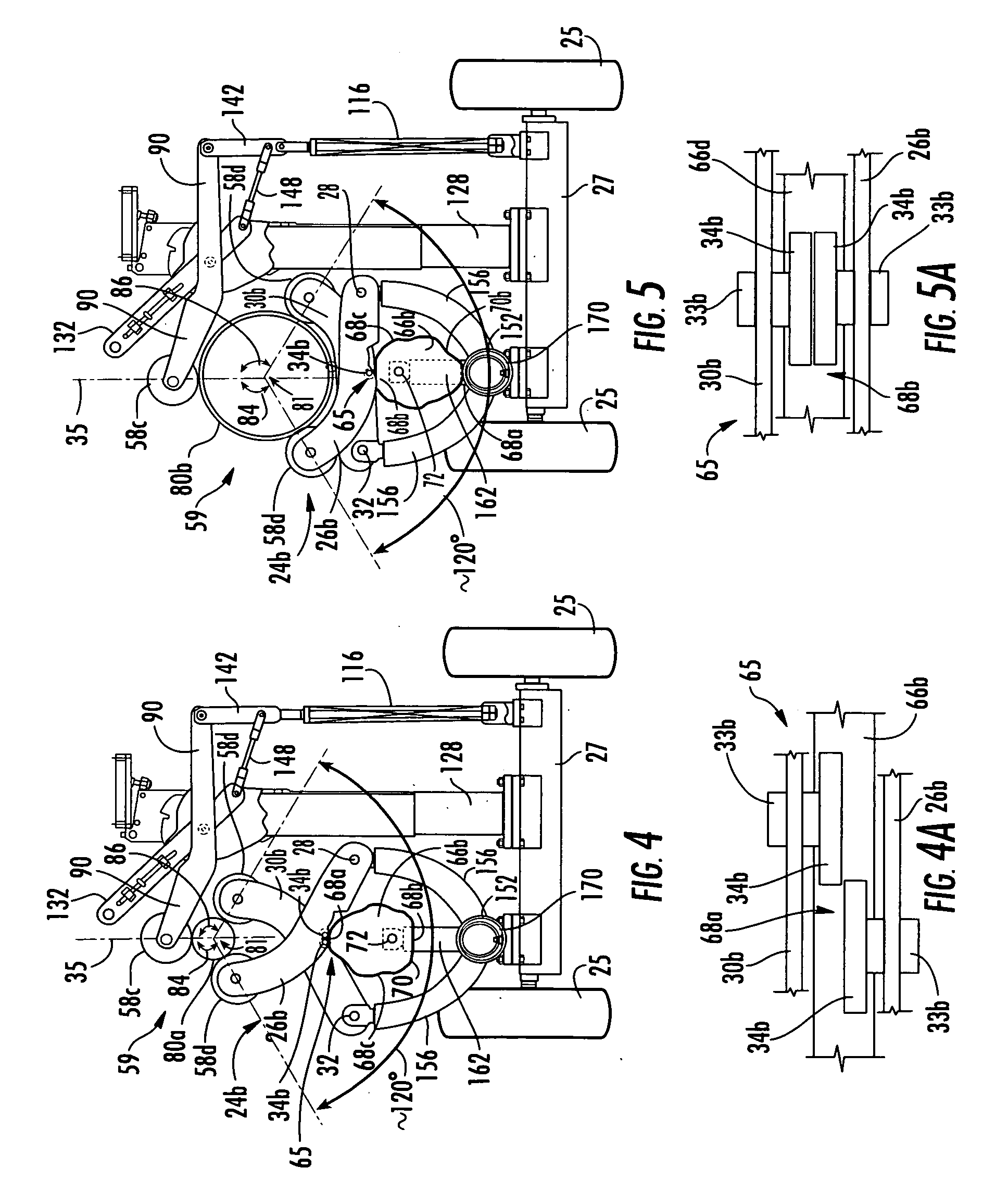
[0060] The frame 22 also includes a series of support arm assemblies 24a-24d which are mounted to bent arms 156. The support arm assemblies 24a-24d are adjustable so that they may be used to support pipes having a variety of different diameters (FIGS. 4 and 5). Support arm assembly 24b is illustrated in FIGS. 4 and 5. Support arm assembly 24b includes a first support arm 26b pivotally mounted to a bent arm 156 of frame 22 with a bolt or other fastener that defines a first pivot axis 28. A second support arm 30b is pivotally mounted to a bent arm 156 of fr...


PUM

PropertyMeasurementUnit
diametersaaaaaaaaaa
diametersaaaaaaaaaa
diametersaaaaaaaaaa

Abstract

A pipe cutting apparatus having a frame and first and second pipe support arms. The pipe support arms are pivotally attached to the frame. First and second pipe support members on the first and second arms together with a third pipe support member securely grip the pipe at substantially equally circumferentially spaced locations. A camming member is used to place the first and second pipe support arms in predefined locations for holding differently sized pipes. An linkage assembly causes the third pipe support member to biasingly engage the pipe. A two-part tool shield is provided together with a depth adjusting assembly for facilitating the cutting and beveling of the pipe. A power transmission assembly transfers power from a motor on the frame to a tool located on a pivoting arm. The frame may be manufactured using an adhesive filler material for enhancing the rigidity, strength and accuracy of the components.

Description

BACKGROUND OF THE INVENTION [0001] 1. Field of the Invention [0002] The present invention relates to a pipe cutting apparatus and, more specifically, to an apparatus for cutting a water or sewer pipe and methods of manufacturing such apparatus. [0003] 2. Description of the Related Art [0004] When installing a water or sewer line, or other similar piping system, it is common to use pipes manufactured of a polymeric material, e.g., polyvinyl chloride (PVC), wherein one end of the pipe is a female end defining a socket and the other end of the pipe is a male end having a beveled outer circumference. The pipes are typically manufactured in standard diameters and lengths and several of the pipes may require cutting in the field to provide pipes having the necessary length. [0005] Typically a rubber gasket is used to seal the joint where two pipes are connected. The gasket is captured within an annular pocket formed on the female end of one of the pipes. The male end of the other pipe eng...

Claims


Application Information

Patent Timeline
Patent Type & Authority Applications(United States)
IPC IPC(8): B23D21/06
CPCB23B5/16B23D45/124B23D33/02B23D21/006Y10T83/222Y10T83/7513Y10T83/7647Y10T83/889Y10T83/9307
Inventor KAEHR, LYLE D.KAEHR, JAMES A.
Owner KAEHR LYLE D
Why Eureka
Try Eureka