Centrifugal pump housing having a flat single cover part

A technology for centrifugal pumps and cover parts, applied in the field of centrifugal pumps, can solve problems such as obstacles

Active Publication Date: 2012-09-19
IHC HOLLAND NV
View PDF1 Cites 0 Cited by
  • Summary
  • Abstract
  • Description
  • Claims
  • Application Information

AI Technical Summary

Problems solved by technology

However, this lifting action is hindered by the reinforcement ring remote from the cover part

Method used


Image

  • Centrifugal pump housing having a flat single cover part
  • Centrifugal pump housing having a flat single cover part
  • Centrifugal pump housing having a flat single cover part

Examples


Embodiment Construction

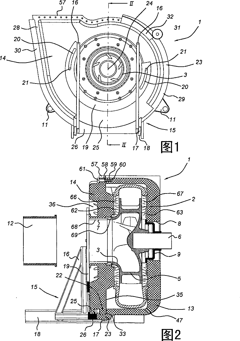
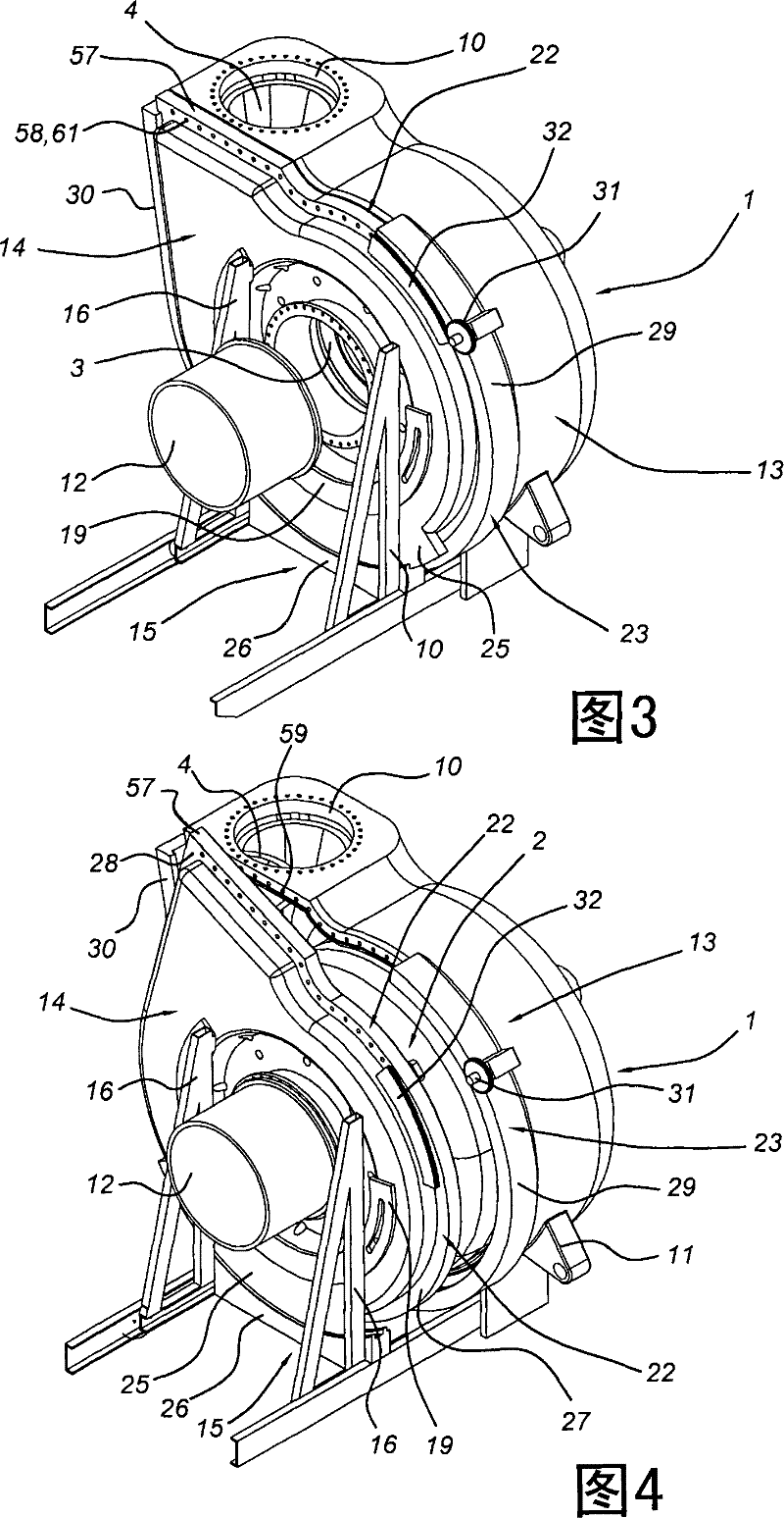
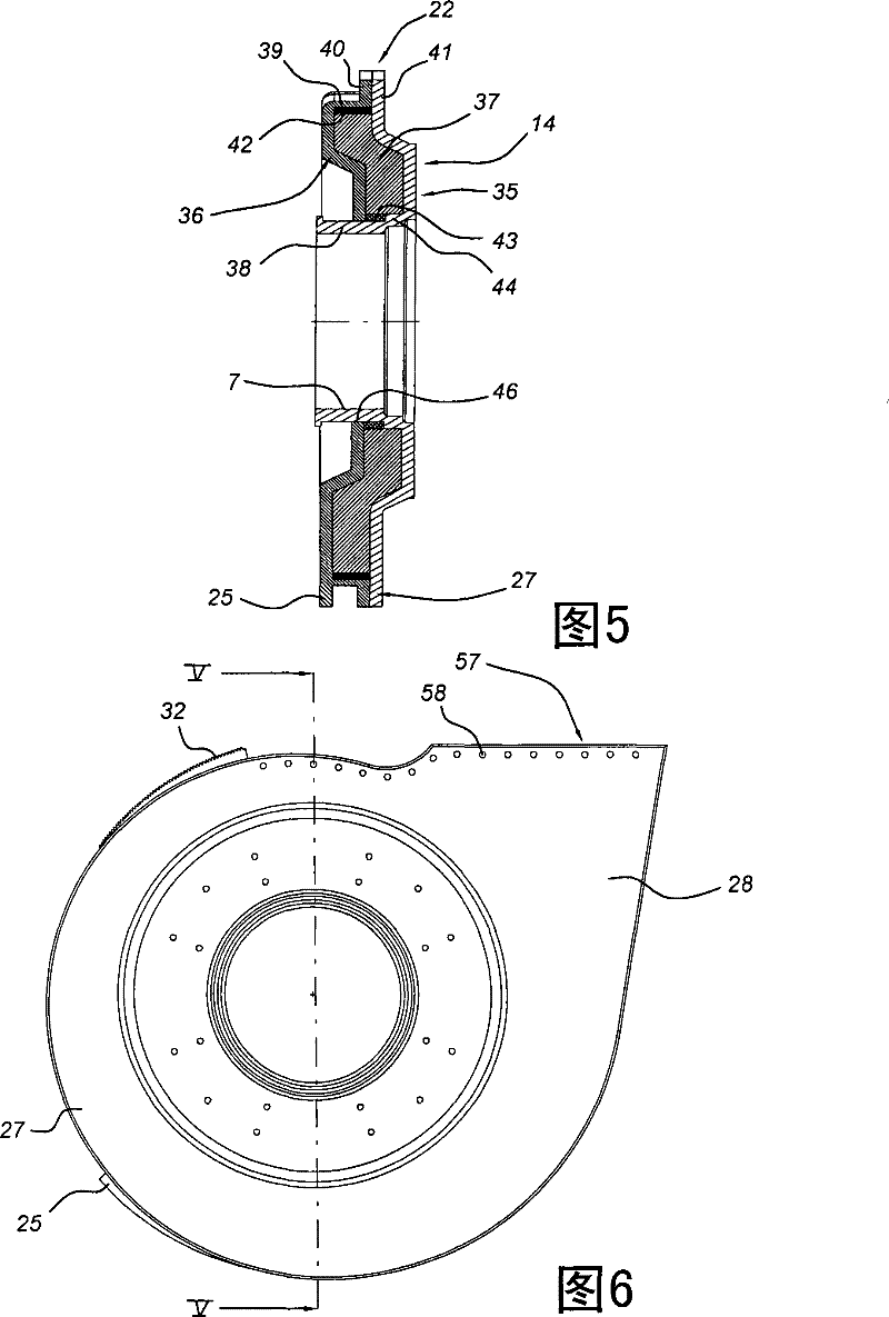
[0031] exist Figure 1-4 The centrifugal pump shown in includes a casing 1, which houses the figure 2 and 4 The inner shell can be seen in 2. The inner shell 2 has a tangentially positioned outlet 4 . The impeller 5 with the suction opening 3 is mounted in the inner housing 2 for rotation about an axis 24 via a drive shaft 6 . Said drive shaft 6 is in turn mounted rotatably in a support (not shown) and connected to a drive motor (not shown).

[0032]Likewise, the casing 1 has a casing inlet opening 7 coaxial with the inlet 3 of the impeller 5 . Due to the overall design of the cover part 14 , the diameter of its inlet opening is smaller than the outer diameter of the impeller 5 . Opposite to the housing inlet opening 7, the housing 1 has a shaft opening 8 through which the drive shaft 6 extends. The drive shaft 6 is sealed relative to the housing 1 by means of the cover 9 . Furthermore, the outer shell 1 has a tangentially positioned outer shell outlet opening 10 which...


PUM


Abstract

The above mentioned invention is related to a centrifugal pump, comprising an outer casing, an inner casing contained in the outer casing, an impeller rotatably supported within the inner casing, an outer casing inlet concentrically arranged with respect to the impeller as well as a tangential outlet, said outer casing comprising a cup shaped part as well as a cover part mounted onto the cup shaped part. The cover part comprises a single element which extends as a unity continuously between the cup shaped part and the outer casing inlet.

Description

technical field [0001] The invention relates to a centrifugal pump comprising a housing, an inner housing housed in the housing, an impeller rotatably supported within the inner housing, a housing inlet arranged concentrically with respect to the impeller and a tangential housing outlet, said housing comprising a cup-shaped part and a mounting A cover part on the cup part, said cover part comprising at least one reinforcing ring. Background technique [0002] Such centrifugal pumps are known. The casing of said prior art centrifugal pump has an inlet cover extending between the inlet and the cover part. Thus, the cover part has a relatively large opening closed by the inlet cover. By removing the inlet cover, an opening in the cover part is opened so that the impeller can be removed through said opening. In this way, the impeller can be replaced without removing the cover part itself. Subsequently, the inlet cover is positioned again between the cover member and the inle...

Claims


Application Information

Patent Timeline
Patent Type & Authority Patents(China)
IPC IPC(8): F04D29/42F04D29/60F04D29/00
CPCF04D7/04F04D29/4286F05D2300/43
Inventor H・H・布达伊哲E・C・范德布洛姆J・库特E・坎特斯
Owner IHC HOLLAND NV
Why Eureka
Try Eureka