Composite flywheel with plastic blade of engine

A technology combining flywheel and wind impeller, which is applied in the direction of engine cooling, engine components, machine/engine, etc., can solve the problems of scrapped flywheel, high brittleness of cast iron material, broken flywheel blades, etc., to reduce manufacturing cost and simplify casting process , The effect of reducing the scrap rate

Inactive Publication Date: 2008-09-24
WUXI KIPOR POWER CO LTD
View PDF0 Cites 5 Cited by
  • Summary
  • Abstract
  • Description
  • Claims
  • Application Information

AI Technical Summary

Problems solved by technology

In addition, during the transportation and assembly process of the finished flywheel, due to the thin wall of the blades and the high brittleness of the cast iron material, the flywheel blades are easily broken, resulting in the scrapping of the entire flywheel

Method used


Image

  • Composite flywheel with plastic blade of engine

Examples


Embodiment Construction

[0011] Below the present invention will be further described in conjunction with the embodiment in the accompanying drawing:

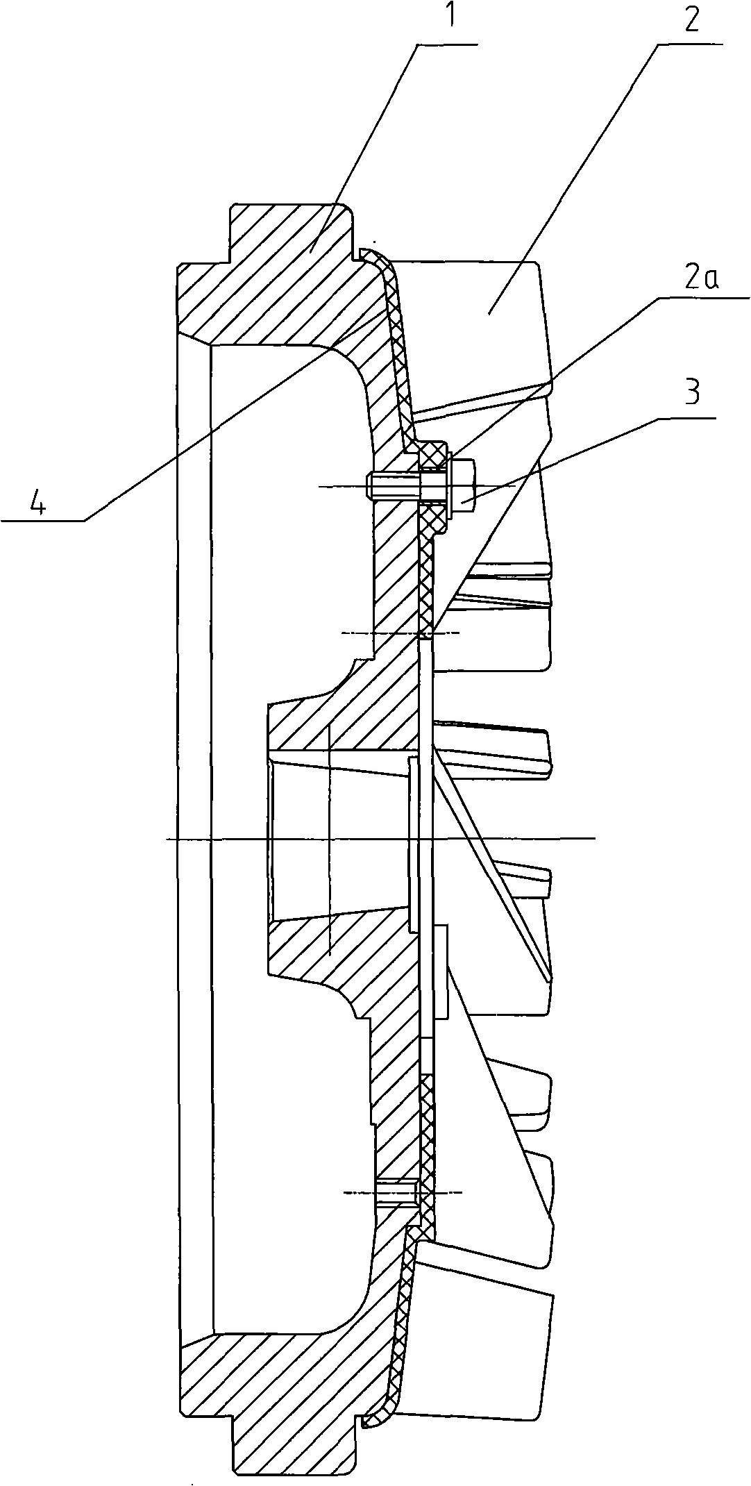
[0012] Such as figure 1 , shown in Fig. 2, mainly comprise flywheel 1, plastic wind impeller 2 (steel bushing 2a), bolt 3 etc.

[0013] In the present invention, the plastic wind impeller 2 is fastened on the screw hole of the flywheel 1 with several bolts 3 . In addition, a steel bushing 2a is cast in the screw hole of the plastic wind impeller 2 to bear the pressing force during locking. In order to prevent the wind impeller 2 from moving radially due to vibration during rotation, the flywheel 1 is processed with a positioning stop circle for the wind impeller. In addition, the two ends of the flywheel 1 and the plastic wind impeller 2 are fitted with inclined planes 4, and the same included angle ensures reliable bonding between the flywheel 1 and the plastic wind impeller 2, effectively preventing the plastic wind impeller 2 from moving radially....


PUM


Abstract

The invention relates to a sectional flywheel with a plastic fan blade for an engine, which is fixed on the front end of an engine crankshaft by a flywheel nut. The invention is characterized in that the invention includes a flywheel and a plastic fan blade which is tightly fixed on the screw hole of the flywheel by a bolt. A steel lining is arranged inside the screw hole of the plastic fan blade. The flywheel is provided with the locating spigot round of the fan blade. The flywheel has a miter joint with the two end planes of the fan blade. The invention changes the whole cast iron flywheel vane into the subassembly of cast iron flywheel and plastic fan blade. With the advantages of simple structure and low manufacture cost, the invention can prevent the vane damage in the casting and transportation process, effectively improving the economical efficiency of the engine and simplifying the casting technology of the flywheel. Reducing the defective index of the cast iron vane, the invention is also favorable for improving the fan efficiency.

Description

technical field [0001] The invention relates to an engine combined flywheel with plastic blades, which is fixed on the front end of the engine crankshaft. Background technique [0002] In the prior art, the engine flywheel usually adopts cast iron material to integrally cast the flywheel and the blades. This structure complicates the casting process of the flywheel. Because the flywheel disc is very thick and the blades are very thin, the thermal stress at the junction of the two is very large, which requires high casting technology. In addition, during the transportation and assembly process of the finished flywheel, due to the thin wall of the blades and the high brittleness of the cast iron material, the flywheel blades are easily broken, resulting in the scrapping of the entire flywheel. Contents of the invention [0003] The purpose of the present invention is to overcome the above disadvantages, thereby providing a combined flywheel with plastic fan blades of the e...

Claims


Application Information

Patent Timeline
Patent Type & Authority Applications(China)
IPC IPC(8): F16F15/30F01P5/02
Inventor 肖亨琳
Owner WUXI KIPOR POWER CO LTD
Why Eureka
Try Eureka