Lens shade correction index confirming method, lens shade emendation method and device

A lens shading and correction coefficient technology, applied in the field of image processing, can solve the problems of poor lens effect and lack of versatility, and achieve good image correction effect

Active Publication Date: 2008-09-24
北京中星天视科技有限公司
View PDF0 Cites 22 Cited by
  • Summary
  • Abstract
  • Description
  • Claims
  • Application Information

AI Technical Summary

Problems solved by technology

However, judging from the processing effect of some actual images, many lenses do not fully conform to this assumption, so a kind of shadow model represented by the fourth p

Method used


Image

  • Lens shade correction index confirming method, lens shade emendation method and device
  • Lens shade correction index confirming method, lens shade emendation method and device
  • Lens shade correction index confirming method, lens shade emendation method and device

Examples


Embodiment 1

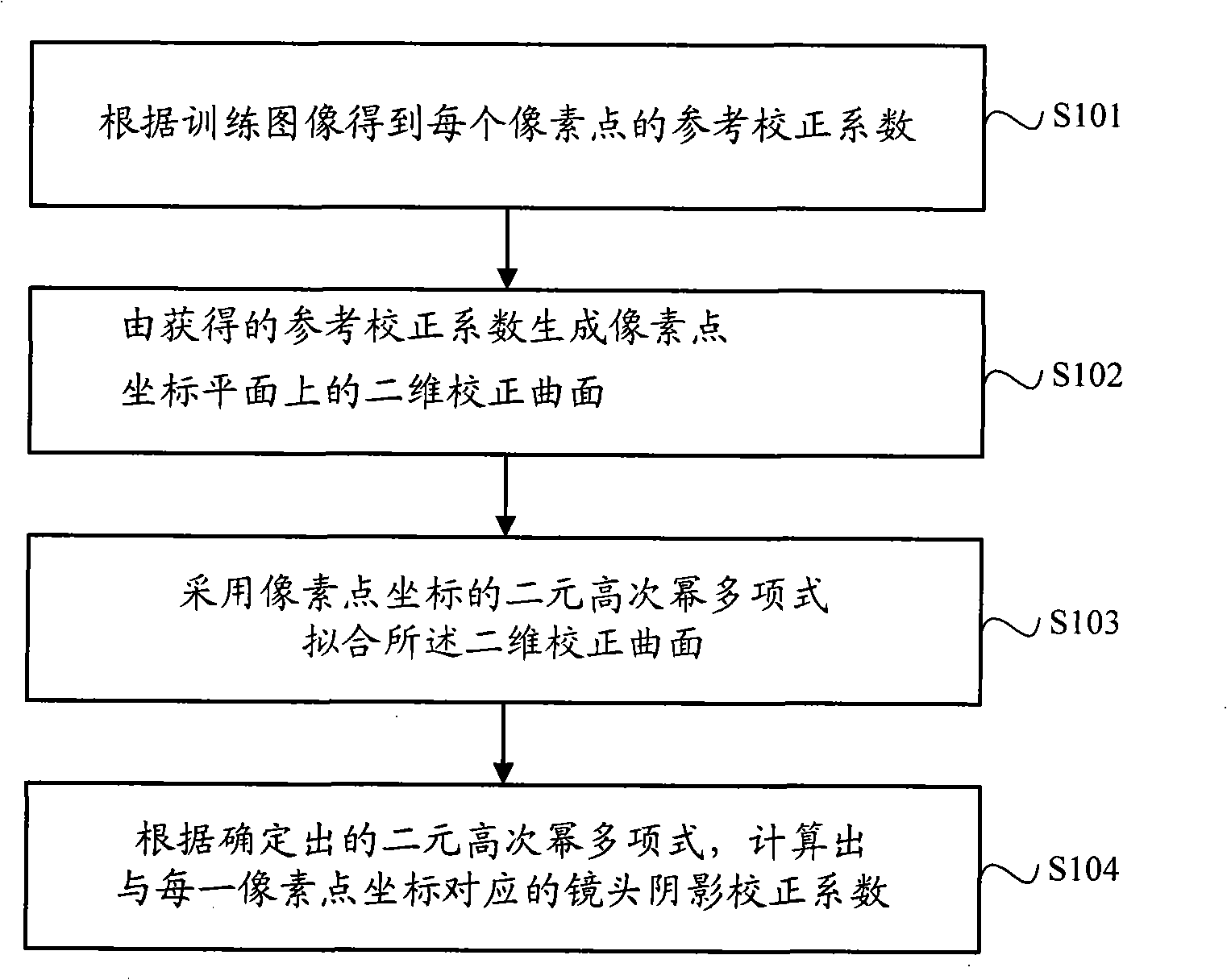
[0054] see figure 1 , providing a lens shading correction coefficient determination method for Embodiment 1 of the present invention, comprising the following steps:

[0055] Step S101. Obtain a reference correction coefficient for each pixel according to the training image.

[0056] Specifically:

[0057] A training image is captured by a lens to obtain a captured image of the training image; wherein, the standard pixel value of each pixel in the training image is known. In practice, for the sake of simplicity, you can use a lens to shoot a piece of white paper with a uniform texture. For example, to obtain a captured image with a size of 640*480, assuming that the standard pixel value of each pixel in the training image is 255, because the lens In the presence of shadows, the pixel value of each pixel in the captured image may change (that is, the real pixel value of each pixel may not be equal to 255). Therefore, the real pixel value of each pixel in the captured image is o...

Embodiment 2

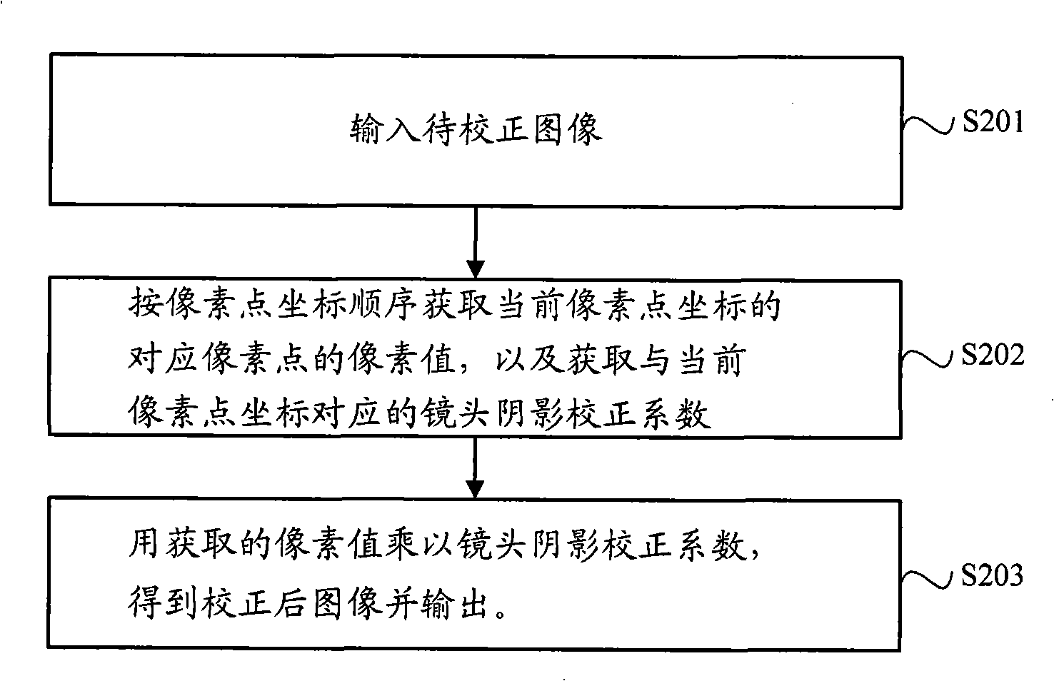
[0098] Embodiment 2 of the present invention provides a lens shading correction method, the specific process is as follows figure 2 shown, including:

[0099] Step S201, inputting an image to be corrected.

[0100] Step S202 , acquiring the pixel value of the pixel corresponding to the current pixel coordinate in order of the pixel coordinates, and acquiring the lens shading correction coefficient corresponding to the current pixel coordinate.

[0101] Specifically: according to the sequence of pixels in the image from top to bottom and from left to right, the pixel values ​​of corresponding pixels are sequentially obtained; and then according to the pixel coordinates corresponding to the pixels, the corresponding lens shading correction coefficients are obtained. Wherein, the lens shading correction coefficient corresponding to each pixel coordinate is determined by using the method described in the first embodiment.

[0102] Step S203: Multiply the acquired pixel value by...

Embodiment 3

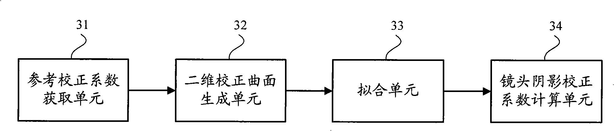
[0111] According to the method for determining the lens shading correction coefficient provided in the first embodiment of the present invention, the third embodiment provides a corresponding device for determining the lens shading correction coefficient, and its structural diagram is as follows image 3 As shown, it includes: a reference correction coefficient acquisition unit 31 , a two-dimensional correction surface generation unit 32 , a fitting unit 33 and a lens shading correction coefficient calculation unit 34 . in:

[0112] Reference correction coefficient acquisition unit 31, for obtaining and outputting the reference correction coefficient of each pixel according to the training image;

[0113] A two-dimensional correction surface generation unit 32, configured to receive the reference correction coefficient output by the reference correction coefficient acquisition unit 31, and generate a two-dimensional correction surface on the pixel coordinate plane;

[0114] T...


PUM


Abstract

The invention discloses a lens shadow correction coefficient confirming method, a lens shadow correcting method and a device thereof, which comprise: the reference correction coefficient of each pixel point is obtained according to a training image; the reference correction coefficient forms a two-dimensional correction curved surface at a pixel point coordinate plane; the binary high-ordered power multinomial of the pixel point coordinate is used for fitting the two-dimensional correction curved surface; the lens shadow correction coefficient corresponding to each pixel point coordinate is calculated according to the multinomial, and an image shot by the lens is processed for lens shadow correction disposal according to the confirmed lens shadow correction coefficient. The method of the invention is suitable for the lens shadow correction for the image shot by various types of lenses, which has good image correction effect and is simple to be realized.

Description

technical field [0001] The invention relates to image processing, in particular to a method for determining a lens shading correction coefficient in an image, a lens shading correction method and a device. Background technique [0002] Lens shadow is a phenomenon that the exposure of the imaging plane is inconsistent due to the inconsistency of the light transmittance of the lens. In the existing methods, it is generally assumed that the center of the lens is the brightest point, and the darkness around the lens is symmetrical. When performing lens shadow processing, it is considered that the ratio of the brightness around the image to the brightness of the center conforms to the optical axis and the distance between the imaging point and the center of the lens. The relationship between the cosine 4th power of the included angle, and the image is corrected for lens shading according to this shading model. Using the above assumptions and shadow model to correct the lens shad...

Claims


Application Information

Patent Timeline
IPC IPC(8): G02B27/00G06T5/00
Inventor 谌安军王浩
Owner 北京中星天视科技有限公司
Why Eureka
Try Eureka