Optical transmission unit frame generating method and device, method and device for transmitting clock rank

A technology of an optical transmission unit and a generating device, which is applied in the field of optical transmission unit frame generation and device and transmission clock level and device, and can solve the problem of undefined clock quality level, clock quality level cannot be transmitted, unfavorable OTN network element clock selection, clock Quality-level transmission of clock protection and recovery issues to achieve the effect of improving network quality and network protection functions, flexible and reliable clock protection switching, and convenient clock selection

Inactive Publication Date: 2008-09-24
ZTE CORP
View PDF0 Cites 5 Cited by
  • Summary
  • Abstract
  • Description
  • Claims
  • Application Information

AI Technical Summary

Problems solved by technology

However, unlike Synchronous Digital Hierarchy (SDH, Synchronous Digital Hierarchy), there is no clock quality level defined in OTN. When the SDH service is connected to OTN, the clock quality level cannot be transmitted.
However, after the network element in the OTN receives the OTN service, although the clock of the OTN service can be recovered, the clock quality level of the OTN service cannot be confirmed. restoration of protection, etc.
For example: OTN network element B tracks the clock of OTN network element A, OTN network element A transmits a data frame carrying clock information for synchronization to OTN network element B, OTN network element B extracts the clock information and selects it as its own clock When OTN NE B transmits a data frame to OTN NE A, because the data frame does not carry the clock quality level information of the clock, OTN NE A will select the clock transmitted by OTN NE B as the clock source, thus Causes the emergence of clock loops, which will inevitably lead to a large amount of data loss

Method used


Image

  • Optical transmission unit frame generating method and device, method and device for transmitting clock rank
  • Optical transmission unit frame generating method and device, method and device for transmitting clock rank
  • Optical transmission unit frame generating method and device, method and device for transmitting clock rank

Examples


Embodiment Construction

[0033] The present invention will be described in detail below in conjunction with the accompanying drawings.

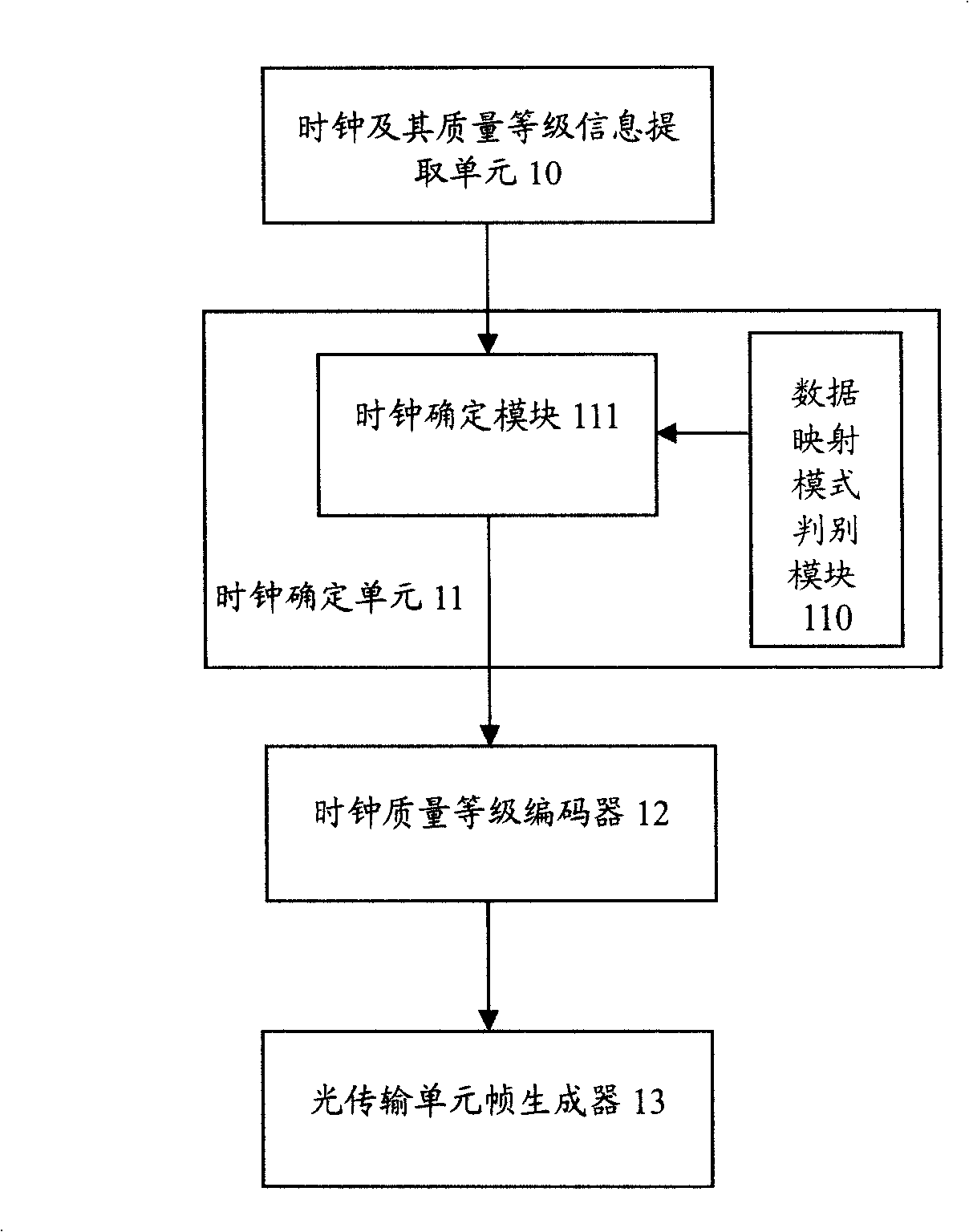
[0034] figure 1 It is a schematic diagram of the composition structure of the generating device of the OTU frame of the present invention, such as figure 1 As shown, the OTU frame generation device of the present invention includes a clock and its quality level information extraction unit 10 , a clock determination unit 11 , a clock quality level encoder 12 and an optical transmission unit frame generator 13 . Wherein, the clock and its quality level information extraction unit 10 are used to extract the clock and its quality level; the clock determination unit 11 is used to determine the clock quality level for the OTU frame to be generated; the clock quality level encoder 12 is used to carry out the clock quality level Encoding; the optical transmission unit frame generator 13 is used to generate an OTU frame.

[0035] When the OTN maps the data in itself to gene...


PUM


Abstract

The invention discloses a generating method for an optical transmission unit frame in an optical transmission network which is proposed for solving the problem that existing optical transmission network can not confirm the quality grade of a clock. The method comprises: A, the clock and the quality grade information thereof of a clock source in the optical transmission network is picked up; B, the clock is confirmed for the optical transmission unit frame to be generated according to the clock and the quality grade information thereof picked up in step A; C, the quality grade corresponding to the clock confirmed in step B is carried out coding, then inserted into a reserved byte of the optical transmission unit frame to be generated. The invention also discloses a device for realizing the method and a method as well as a device utilizing the optical transmission unit frame to transmit the clock quality grade information. The invention is convenient for the optical transmission network to realize synchronization and improves the network quality of the optical transmission network and the network protection function.

Description

technical field [0001] The present invention relates to frame generation and frame-based information transmission technology in an optical transport network (OTN, Optical Transport Network), in particular to a method and device for generating an optical transport unit (OTU, Optical Transport Unit) frame in an optical transport network and using the OTU A method and device for transmitting clock quality level information in a frame. Background technique [0002] In the communication network, a unified clock signal source is to ensure that the clock frequency and phase of all switching nodes are controlled within a predetermined tolerance range, so that all digital streams of each switching node can be exchanged correctly and effectively to achieve the purpose of network synchronization. If the clock signals are inconsistent, it will cause overflow and emptying of information bits in the data buffer, resulting in sliding damage of the digital stream, resulting in data errors. ...

Claims


Application Information

Patent Timeline
Patent Type & Authority Applications(China)
IPC IPC(8): H04J14/08H04J3/06
Inventor 涂勇邓兵倪宝耿健
Owner ZTE CORP
Why Eureka
Try Eureka