Unlock instant, AI-driven research and patent intelligence for your innovation.

Transmission

A transmission and speed change gear technology, applied in couplings, clutches, mechanical drive clutches, etc., can solve the problems of not being able to supply lubricating oil to clutch gears, affecting speed change performance, clutch gear wear, etc., and achieving the effect of improving wear resistance.

Active Publication Date: 2008-09-24
NISSAN MOTOR CO LTD
View PDF1 Cites 4 Cited by
  • Summary
  • Abstract
  • Description
  • Claims
  • Application Information

AI Technical Summary

Problems solved by technology

[0005] However, in the above-mentioned transmission, if the sleeve abuts against the side of the driven gear, the lubricating oil cannot be supplied to the clutch gear, so the clutch gear is worn, which may affect the transmission performance.

Method used


Image

  • Transmission
  • Transmission
  • Transmission

Examples


Embodiment Construction

[0022] Hereinafter, embodiments of the present invention will be described based on the drawings.

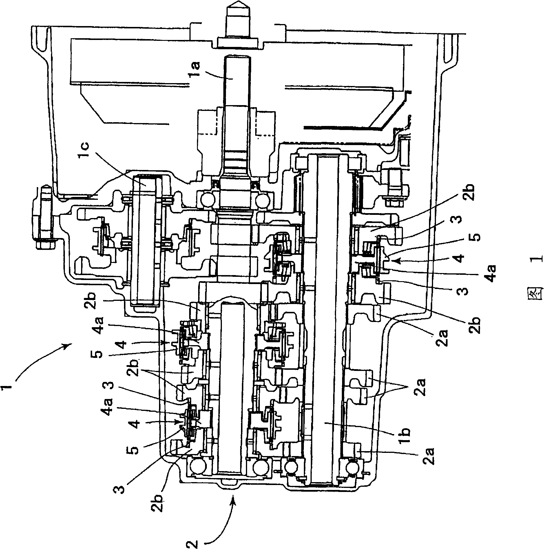
[0023] FIG. 1 is a schematic configuration diagram showing a transmission.

[0024] As shown in the figure, the transmission 1 of the embodiment has an input shaft 1a, an output shaft 1b, an intermediate shaft 1c for reverse gear, a transmission gear mechanism 2, and a synchronizer 4. The output shaft 1b, the intermediate shaft 1c for reverse gear and the input shaft 1a Arranged in parallel, the speed change gear mechanism 2 is disposed on each of these shafts, and transmits the power of the output shaft 1a to the output shaft 1b or the counter shaft 1c for reverse gear after changing the speed, and the synchronizer 4 synchronizes the meshing gears.

[0025] The speed change gear mechanism 2 is configured as a well-known helical gear, and has a fixed gear 2a fixedly mounted on each shaft and an idler gear 2b mounted idly on each shaft. The clutch gear 3 is integrally formed wit...


PUM


Abstract

A transmission comprising a clutch gear (3) rotatable integrally with a speed change gear (2), a coupling sleeve (5) connectable to the clutch gear (3) by slidably moving on the outer peripheral surface of a synchronizer hub, a stopper (7) for allowing the end face (5b) of the coupling sleeve (5) to abut thereon to restrain the slidable movement of the coupling sleeve (5) to the speed change gear (2) side, and a lubrication groove (6) capable of feeding a lubricating oil to the clutch gear (3) when the coupling sleeve (5) abuts on the stopper (7).

Description

technical field [0001] The invention relates to a transmission. Background technique [0002] Conventionally, as this type of transmission, as disclosed in Patent Document 1, a transmission having a driven gear, a clutch gear, and a sleeve, the driven gear being rotatably supported on an intermediate shaft, has been proposed. The clutch gear is arranged on the outer periphery of the driven gear on the blocking ring side, and the sleeve is configured to slide axially on the outer peripheral surface of the hub, so that the sleeve moves to the driven gear side and the The sleeve meshes with the clutch gear, and is in a meshed state that connects the intermediate shaft and the driven gear. [0003] In this transmission, the outer diameter of the driven gear is formed larger than the inner diameter of the sleeve, and the shift speed is determined by shifting the sleeve so that it abuts against the side surface of the driven gear. [0004] Patent Document 1: Japanese Patent No. ...

Claims


Application Information

Patent Timeline
Patent Type & Authority Applications(China)
IPC IPC(8): F16D23/06F16H57/04
CPCF16D23/06F16D2300/06F16H57/0478F16H57/0494
Inventor 青山英树泽木康宏中村勉
Owner NISSAN MOTOR CO LTD